Automatic molding system for biomass flat-die particle

A technology of biomass and flat die, which is applied in the direction of mold extrusion granulation, biofuel, waste fuel, etc., can solve the problems of poor connection of flat die forming, complicated equipment, short maintenance cycle, etc., and improve technology integration Horizontal, reduced maintenance, wide diameter range

Inactive Publication Date: 2012-06-27
ENERGY RES INST CO LTD HENAN ACADEMY OF SCI
View PDF5 Cites 13 Cited by
  • Summary
  • Abstract
  • Description
  • Claims
  • Application Information

AI Technical Summary

Problems solved by technology

(1) The theoretical foundation of flat die forming is weak, and the research on the forming characteristics and mechanism of biomass is not systematic and in-depth. At present, there is no development and application of biomass flat die technology and equipment; (2), the main components and equipment are severely worn , short maintenance cycle, high energy consumption, etc., and the research on integrated and automated biomass flat die molding is still immature, and the connection between flat die molding and other equipment such as drying equipment and crushing equipment is not very good; (3) 1. Flat die molding lacks diversity in molds, and it is difficult to meet the needs of different biomass utilization equipment; (4) Overseas biomass flat die compression molding technology is relatively mature, and some countries such as Northern Europe have formed a large industrial scale, but the equipment Complex, high cost, and the applicable raw material is mainly forestry biomass, which is not suitable for my country's national conditions

Method used


Image

  • Automatic molding system for biomass flat-die particle
  • Automatic molding system for biomass flat-die particle

Examples


Embodiment Construction

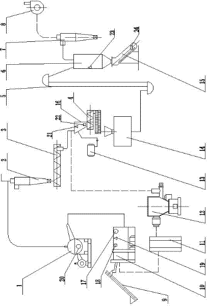
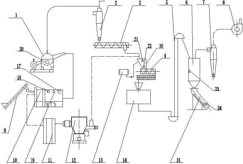
[0030] Such as figure 1 As shown, the biomass flat die granule automatic molding system of the present invention includes a drying part, a pulverizing part, a material conveying part, a molding part and a cooling and drying separation part, the discharge port of the drying part is connected with the feeding port of the pulverizing part, and the pulverizing The discharge port of the part is connected with the feed port of the forming part through the material conveying part, and the discharge port of the forming part is connected with the feed port of the cooling, drying and separating part.

[0031] The drying part includes a fluidized gasifier 12, a settling chamber 11 and a drier 10. The hot gas outlet of the fluidized gasifier 12 is connected to the air inlet of the drier 10 through the settling chamber 11. The feed inlet of the drier 10 is provided with an upper The feeder 9; the dryer 10 is provided with a first current sensor 17, a first humidity sensor 18 and a first te...


PUM

PropertyMeasurementUnit
particle diameteraaaaaaaaaa
densityaaaaaaaaaa
thermal efficiencyaaaaaaaaaa

Abstract

The invention discloses an automatic molding system for a biomass flat-die particle, which comprises a drying part, a crushing part, a material conveying part, a molding part and a cooling and drying separating part, wherein the discharge hole of the drying part is connected with the feeding hole of the crushing part; the discharge hole of the crushing part is connected with the feeding hole of the molding part through the material conveying part; and the discharge hole of the molding part is connected with the feeding hole of the cooling and drying separating part. The automatic molding system for the biomass flat-die particle includes a set of intelligent and automatic large-scale energy treatment process routes integrating straw drying, straw crushing and straw cold-state compact molding. According to the automatic molding system for the biomass flat-die particle, the automatic operation of all links of biomass molding is realized by adopting an integral automatic control system, thereby, manual operations are reduced, and the automatic operation of the system under optimized working conditions is ensured; energy consumption and labor cost are low; and a heat source is provided by adopting the fluidized-bed combustion technology in the biomass drying process without consuming traditional energy sources, and the heat utilization efficiency of equipment can reach over 60 percent.

Description

technical field [0001] The invention belongs to the technical field of biomass fuel preparation, in particular to an automatic molding system for biomass flat die particles. Background technique [0002] The development of foreign briquette fuels is divided into three stages: from the 1930s to the 1950s is the stage of research, demonstration, and cross-introduction, and the focus of research is to replace fossil energy; the second stage is from the 1970s to the 1990s. The impact of fossil energy on the environment has been generally paid attention to, and interest in a large amount of renewable biomass energy has been developed, and research on biomass compact briquette fuel has been carried out. A relatively large number of biomass densified briquette fuels are used; from the late 1990s to the present, it is the third stage. First, the research work on large-scale utilization was carried out led by Denmark. The famous Danish energy investment company BWE took the lead in d...

Claims


Application Information

Patent Timeline
Patent Type & Authority Applications(China)
IPC IPC(8): C10L5/44B01J2/22
CPCY02E50/30Y02E50/10
Inventor 杜金宇
Owner ENERGY RES INST CO LTD HENAN ACADEMY OF SCI
Why Eureka
Try Eureka