

Small-size precombustion chamber for engine
A pre-combustion chamber and engine technology, applied in the direction of combustion chamber, continuous combustion chamber, combustion method, etc., can solve the problems of large size of combustion chamber, troublesome installation, failure to meet assembly requirements, etc., and achieve small size, easy installation, good fuel consumption, etc. The effect of atomization and stabilization of the low-velocity ignition zone
- Summary
- Abstract
- Description
- Claims
- Application Information
AI Technical Summary
Problems solved by technology
Method used
Image

Examples
Embodiment 1
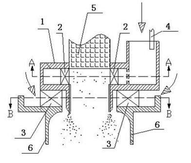
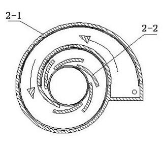
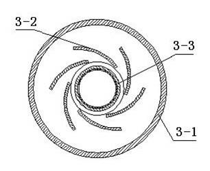
[0028] Such as figure 1 , figure 2 and image 3 Shown, a kind of small-sized pre-chamber of engine, it comprises: pre-chamber body 1, the primary swirler 2 installed in pre-chamber body 1, secondary swirler 3, fuel injection rod 4 and ignition electric Nozzle 5, the ignition nozzle 5 is vertically installed on the center line of the primary swirler 1 and the secondary swirler 2, and the fuel injection rod 4 is inserted into the oil inlet channel connected with the primary swirler 2 Inside, the first-stage cyclone 2 includes a volute 2-1, a swirl vane 2-2, and a throat of a flow channel is provided at the outlet of the swirl vane 2-2, and the second-stage cyclone 3 includes a housing 3-1, a swirl vane 3-2, a venturi tube 3-3, a throat with a flow channel at the outlet of the swirl vane 3-2, and the first-stage swirler 2 The rotation directions of the swirl blades 2-2 and the swirl blades 3-2 on the secondary swirler 3 are opposite.
[0029] The small-sized pre-chamber of ...
Embodiment 2
[0033] 1. The internal flow characteristic detection of the small-sized pre-combustion chamber of the engine provided by the present invention: using commercial computational fluid dynamics software fluent6.3, a full three-dimensional numerical simulation of the pre-combustion chamber is carried out. Using the K-e turbulence model and the SIMPLE algorithm, the discreteness of each parameter Both adopt the second-order upwind scheme, and the criterion for solution convergence is that the residual error of the continuous equation is not greater than 10 -6 ; The inlet is set as a pressure boundary condition (gauge pressure 15000pa), and the outlet is set as a free boundary, which is the ambient pressure. The numerical test results show that under the action of the rotating air flow, a pair of recirculation zones such as Figure 4 As shown, the formed recirculation zone is not easily affected by changes in the upstream air flow, making the pre-chamber ignition stable; and as Figu...
PUM
 Abstract
Description
Claims
Application Information