Pre-splitting blasting method for joint-cutting pipe

A technology of pre-splitting blasting and slotting, which is applied in the field of slotted pipe pre-splitting blasting, which can solve the problems of large consumption of explosives and other materials, increase of project cost, and influence of work efficiency, so as to save blasting equipment and speed up the progress of the project , the effect of improving work efficiency

Inactive Publication Date: 2012-06-27
LANZHOU UNIVERSITY
View PDF4 Cites 11 Cited by
  • Summary
  • Abstract
  • Description
  • Claims
  • Application Information

AI Technical Summary

Problems solved by technology

However, this blasting method has a large number of drill holes, consumes a lot of explosives and other mate

Method used


Image

  • Pre-splitting blasting method for joint-cutting pipe
  • Pre-splitting blasting method for joint-cutting pipe
  • Pre-splitting blasting method for joint-cutting pipe

Examples


Example Embodiment

[0034] Example 1 Slotted pipe pre-splitting blasting method (such as figure 1 , Figure 5 Shown), including the following steps:

[0035] (1) According to the design requirements of millisecond blasting, delimit the peripheral outline of the blasting excavation area, and arrange millisecond blasting holes in the main blasting excavation area.

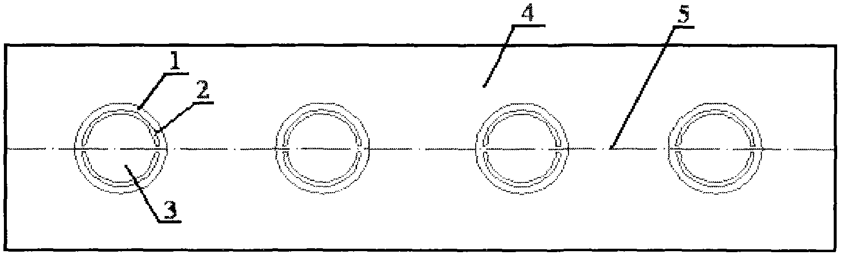
[0036] (2) Arrange pre-splitting blasting holes 1 along the outline of the blasting excavation area.

[0037] Among them: the diameter of the pre-splitting blasting hole 1 is 38-42mm, and the hole spacing of the pre-splitting blasting hole 1 is 15-40 times the diameter of the pre-splitting blasting hole 1.

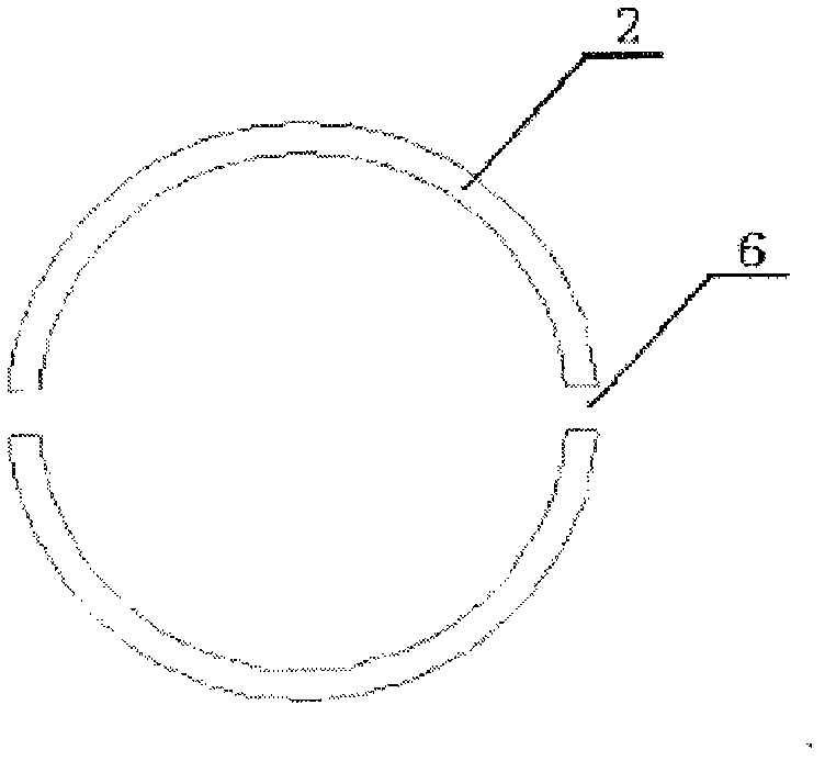
[0038] (3) Place the slit tube 2 in the pre-splitting blast hole 1, so that the two slits of the slit pipe 2 are in the plane formed by the axis of the pre-splitting blast hole 1, that is, in the plane of the pre-slit 5 to be formed .

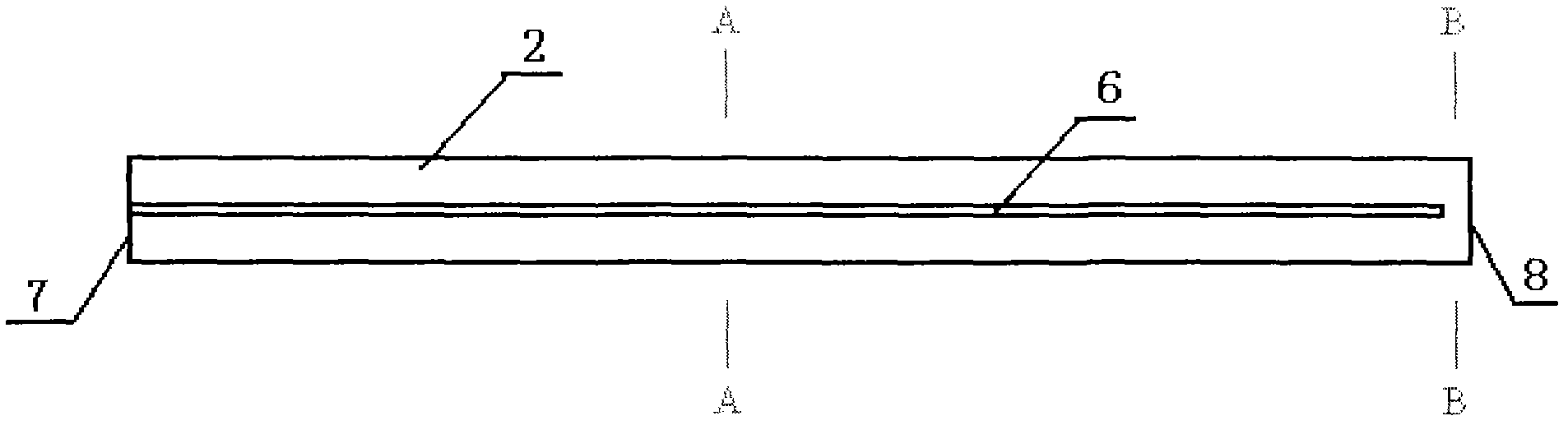
[0039] Among them: the slit tube 2 refers to a hollow tube with a closed bottom end 7 and an open top end ...

Example Embodiment

[0046] Example 2 Pre-splitting blasting method of slit pipe (such as figure 1 , Figure 5 Shown), including the following steps:

[0047] (1) According to the design requirements of millisecond blasting, delimit the peripheral outline of the blasting excavation area, and arrange millisecond blasting holes in the main blasting excavation area.

[0048] (2) Arrange pre-splitting blasting holes 1 along the outline of the blasting excavation area.

[0049] The pre-split blast hole 1 is the same as in Example 1.

[0050] (3) Place the slit tube 2 in the pre-splitting blast hole 1, so that the two slits of the slit pipe 2 are in the plane formed by the axis of the pre-splitting blast hole 1, that is, in the plane of the pre-slit 5 to be formed .

[0051] The slit tube 2 is the same as in Example 1.

[0052] (4) According to the type of rock mass 4, blast charge 3 on the slit tube 2 in the pre-split blasting hole 1, and deploy a low-section detonator. The linear charge density of rock mass 4 ...


PUM

PropertyMeasurementUnit
Diameteraaaaaaaaaa
Wall thicknessaaaaaaaaaa

Abstract

The invention relates to a pre-splitting blasting method for a joint-cutting pipe. The method comprises the following steps: (1) defining a peripheral profile line for a blasting excavation region, and arranging a micro-difference blasting hole in a main body blasting excavation region; (2) arranging a pre-splitting blasting hole along the peripheral profile line in the blasting excavation region; (3) placing the joint-cutting pipe in the pre-splitting blasting hole, and enabling two cut joints of the joint-cutting pipe to be in a plane formed by a shaft line of the pre-splitting blasting hole; (4) performing blasting charge on the joint-cutting pipe in the pre-splitting blasting hole, and arranging low section detonators; (5) performing blasting charge on the micro-difference blasting hole in the main body blasting excavation region, and arranging micro-difference blasting detonators at intervals at a position higher than the pre-splitting blasting hole by two sections; (6) blocking the micro-difference blasting hole and the pre-splitting blasting hole in the main body blasting excavation region; (7) connecting a priming network for blasting; (8) deslagging; and (9) repeating the steps (1) to (8) until completion of excavation. According to the pre-splitting blasting method provided by the invention, the pre-crack forming quality is improved and the engineering cost is decreased while the damage and cracking of a reserved rock body are reduced.

Description

Technical field [0001] The invention relates to a pre-splitting blasting method in the field of controlled blasting, in particular to a slit-cut pipe pre-splitting blasting method. Background technique [0002] The pre-split blasting method is to drill dense blast holes parallel to each other on the excavation contour line, charge explosives and detonators of the same section, and make them detonate before other blast holes. When the blasthole spacing, quantity and charge structure on the contour line When appropriate, after blasting, inter-connecting cracks or pre-cracks will be formed between each blasting hole, which separates the rock mass at the excavation site of the main body from the rock mass that needs to be retained, and then blasts the rock mass at the excavation site of the main body. The pre-cracks on the line have been formed, so the rock mass at the main excavation site will not cause damage to the retained rock mass when blasting, and the retaining rock mass wall...

Claims


Application Information

Patent Timeline
IPC IPC(8): F42D1/00
Inventor 言志信江平
Owner LANZHOU UNIVERSITY
Why Eureka
Try Eureka