Manufacturing process for optical fiber coupler

An optical fiber coupler and manufacturing process technology, applied in the coupling of optical waveguides and other directions, can solve the problems of sensitive splitting ratio and output splitting ratio, and achieve the effects of high reliability, stable temperature characteristics and low additional loss.

Inactive Publication Date: 2012-06-27
COMCORE OPTICAL TECH
View PDF6 Cites 22 Cited by
  • Summary
  • Abstract
  • Description
  • Claims
  • Application Information

AI Technical Summary

Problems solved by technology

However, no matter what kind of fiber is used, the output splitting ratio of the current coupler is very sensitive to different input polarizations, and the shorter the shot length of the polarization-maintaining fiber, the splitting ratio changes with the polarization state after the coupler is made. more sensitive

Method used


Image

  • Manufacturing process for optical fiber coupler
  • Manufacturing process for optical fiber coupler
  • Manufacturing process for optical fiber coupler

Examples


Embodiment Construction

[0047] The optical fiber coupler of the present invention adopts the production process of first grinding and then melting, that is, firstly grinding two optical fibers respectively, then bonding the grinding surfaces of the two optical fibers, and using a high-temperature heating source to melt the two optical fibers together; finally continue to melt Or perform tapering to obtain a fiber coupler with the required splitting ratio.

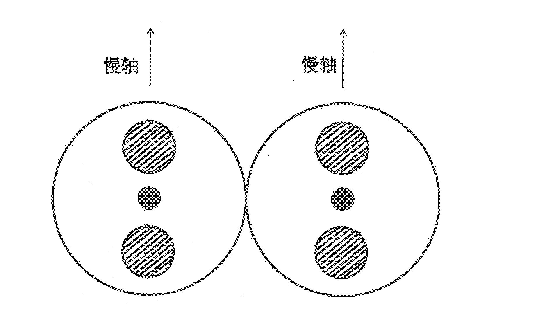
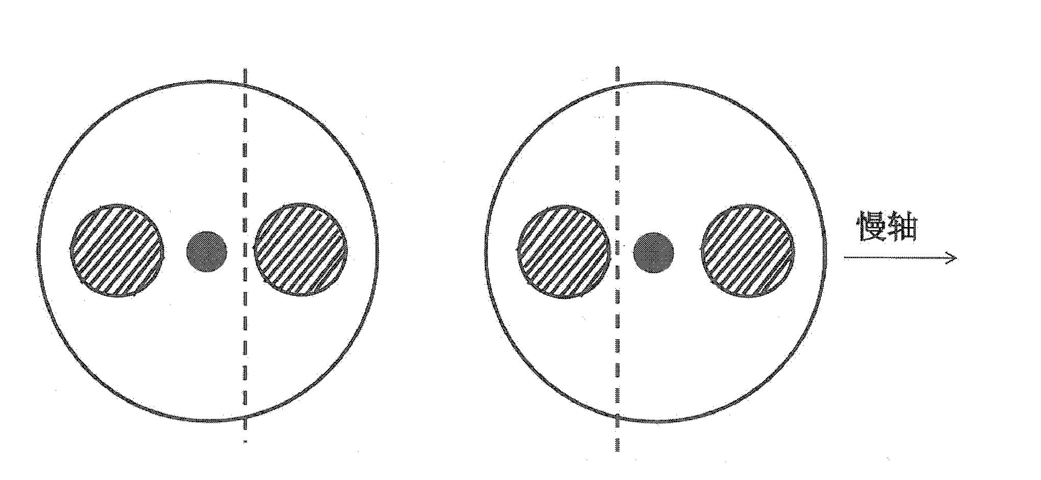
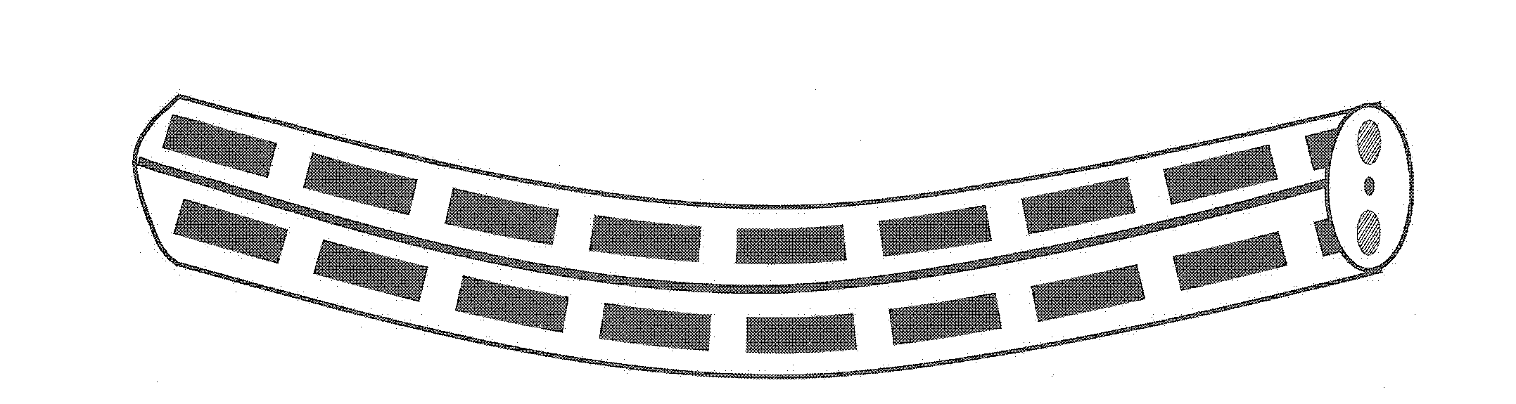
[0048] Taking panda optical fiber as an example, the two optical fibers are positioned first, and then polished separately. The depth of grinding is as follows: figure 2 As shown, that is, one of the stress regions is ground away, while the fiber core and the other stress region are retained, and the two are repeatedly ground according to the aforementioned method. In order to ensure the predetermined depth and length of grinding, the optical fiber must maintain a fixed large bending state (such as a parabola) before grinding, such as Figure 3a...


PUM

PropertyMeasurementUnit
lengthaaaaaaaaaa
lengthaaaaaaaaaa

Abstract

The invention discloses a manufacturing process for an optical fiber coupler, which includes: firstly, respectively grinding two optical fibers; secondly, combining two grinded surfaces; fusing the grinded surfaces by a high-temperature heating source; and finally, precisely controlling the splitting ratio of the coupler by the process of continuous fusing or biconical taper. The manufacturing process can be used for manufacturing a high-performance polarization maintaining optical fiber coupler, a single-mode optical fiber coupler, a multi-mode optical fiber coupler and a multi-mode coupler with a splitting ratio unrelated to an input wavelength and an activation pattern, the polarization maintaining optical fiber coupler and the single-mode optical fiber coupler manufactured by the manufacturing process have the advantages of short coupled area, high reliability, fine temperature property, polarization independence, wavelength independence and the like, and the multi-mode optical fiber coupler manufactured by the manufacturing process has quite high reliability besides quite low added loss.

Description

technical field [0001] The invention relates to the fields of optical fiber communication and optical fiber sensing, in particular to a manufacturing process of an optical fiber coupler. Background technique [0002] With the continuous development of optical fiber communication and optical fiber sensing technology, and the application of polarization maintaining fiber coupler in high-precision fiber optic gyroscope, its usage is increasing, and its performance requirements are also getting higher and higher, and it is required to maintain production The optical fiber of the partial coupler adopts the same optical fiber as the optical fiber gyro ring, which can reduce the splicing loss of the device pigtail and other optical fibers in the gyroscope, which can not only improve the signal-to-noise ratio of the gyroscope, but also greatly improve the production efficiency. In order to reduce the diameter of the fiber optic gyro ring, that is, to increase the curvature of the fi...

Claims


Application Information

Patent Timeline
Patent Type & Authority Applications(China)
IPC IPC(8): G02B6/255
Inventor 黄勇
Owner COMCORE OPTICAL TECH
Why Eureka
Try Eureka