Eutectic welding machine for die bonding of LED (Light Emitting Diode) chip

A LED chip and eutectic soldering technology, which is applied in semiconductor/solid-state device manufacturing, electrical components, circuits, etc., can solve problems such as chip thermal damage, chip function failure, and large temperature balance error of the heating system, so as to achieve thermal damage Small, the effect of ensuring wettability

Active Publication Date: 2012-06-27
SHANGHAI GONGJING ELECTRONICS TECH
View PDF4 Cites 11 Cited by
  • Summary
  • Abstract
  • Description
  • Claims
  • Application Information

AI Technical Summary

Problems solved by technology

[0003] 1. The non-selective common heating method of the chip and the bracket is easy to cause thermal damage to the chip, resulting in the failure of the chip function
[0004] 2. The temperature control of the heating system is relatively extensive, and the sampling frequency of the temperature control point is 1KHz; resulting in a large error in the temperature balance of the heating system, and it is impossible to realize multi-point synchronous sharing; it is limited to single-piece production
[0005] 3. No eutectic welding interface wettability process guarantee system, which limits the quality consistency and reliability of eutectic welding

Method used


Image

  • Eutectic welding machine for die bonding of LED (Light Emitting Diode) chip
  • Eutectic welding machine for die bonding of LED (Light Emitting Diode) chip

Examples


Embodiment

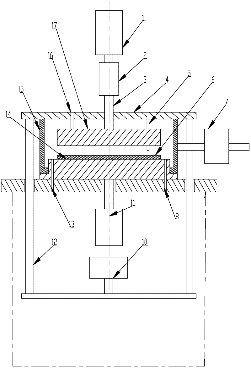
[0026] Such as figure 1 As shown, a eutectic welding machine for LED chip solidification, including a eutectic tray 15, a targeting heating plate 14, a sealing plate 4, a chip pressing heat conducting plate 17, a resonant transducer 2, and a resonant horn 3. The eutectic tray 15 is used to place the LED chip 6, and is provided with a stepping motor feed mechanism 7 that can drive the eutectic tray 15 to move horizontally. The interface combined with the support is highly directional heated. The targeting heating plate 14 is provided with a heating plate driving cylinder 11, which can be driven by the heating plate driving cylinder 11 to be close to the bottom of the eutectic tray 15, and the sealing plate 4 is arranged above the eutectic tray 15, and the sealing plate 4 passes through the guide The column 12 is connected with the sealed flat cylinder 10, and can be tightly sealed with the upper end of the eutectic tray 15 driven by the sealed flat cylinder 10 to form a close...


PUM


Abstract

The invention relates to a eutectic welding machine for die bonding of an LED (Light Emitting Diode) chip. The eutectic welding machine comprises a eutectic tray on which a step motor feeding mechanism capable of driving the eutectic tray to move horizontally is arranged, a target heating plate which is arranged below the eutectic tray and on which a heating plate drive cylinder used for driving the target heating plate to cling to the bottom of the eutectic tray is arranged, a sealing flat plate which is arranged above the eutectic tray, is connected with a sealing flat plate cylinder and is tightly combined with the upper end of the eutectic tray under the driving effect of the sealing flat plate cylinder to form a sealed cavity body, a chip compacting heat-conducting plate which is arranged in the sealed cavity body and is provided with a temperature sensor, a resonance energy conversion assembly which is connected with the chip compacting heat-conducting plate and is provided with a resonance cylinder, and an air pipeline assembly communicated with the inner part and the outer part of the sealed cavity body. Compared with the prior art, the eutectic welding machine for the die bonding of the LED chip has the advantages of good eutectic welding interface wettability, stable welding quality, small heating temperature balance error and the like.

Description

technical field [0001] The invention relates to a eutectic welding machine, in particular to a eutectic welding machine used for solid crystal of LED chips. Background technique [0002] At present, the eutectic welding machines used for LED semiconductor chip solidification are all used for single-piece and small-batch production; due to the limitations of technology and design reasons, their performance cannot meet the requirements of high-quality mass production. It mainly has some defects: [0003] 1. The non-selective common heating method of the chip and the bracket is easy to cause thermal damage to the chip, resulting in the failure of the chip function. [0004] 2. The temperature control of the heating system is relatively extensive, and the sampling frequency of the temperature control point is 1KHz; resulting in a large error in the temperature balance of the heating system, and it is impossible to realize multi-point synchronous sharing; it is limited to single...

Claims


Application Information

Patent Timeline
Patent Type & Authority Applications(China)
IPC IPC(8): H01L21/60H01L33/00
Inventor 马明驼
Owner SHANGHAI GONGJING ELECTRONICS TECH
Why Eureka
Try Eureka