
Method for calibrating sound pressure in low-frequency sound wave free field

A technology of low-frequency sound wave and calibration method, which is applied in the direction of ultrasonic/sonic wave/infrasonic wave transmission system, transmission monitoring, electrical components, etc. It can solve the problems of medium impure resonance, frequency limitation, interference, etc., and achieve simple and convenient implementation and expansion of frequency Lower bound, method reliable effect

Active Publication Date: 2012-06-27
THE 715TH RES INST OF CHINA SHIPBUILDING IND CORP
View PDF1 Cites 10 Cited by
  • Summary
  • Abstract
  • Description
  • Claims
  • Application Information

AI Technical Summary

Problems solved by technology

However, the disadvantage of the traditional pulse method is: as the frequency decreases, the wavelength of the sound wave increases, and the effect of the pulse method also decreases or even cannot be applied, which also limits the lower limit of the frequency of free field calibration.
[0055] (2) Regular electroacoustic signal interference
[0056] (3) Electric cross-leakage interference
[0057] (4) Interface reflection and standing wave interference between sending and receiving sensors
[0058] (5) Resonance interference caused by impure medium
However, as the calibration frequency decreases, the wavelength of the acoustic wave increases, and the pulse width of the required pulse signal also increases accordingly, resulting in a larger size requirement for the calibration area in order to use the conventional pulse method to distinguish the direct acoustic pulse from the time domain. reflected sound pulse
Therefore, for a certain size of indoor calibration area, as the frequency continues to decrease, the effectiveness of the conventional pulse technology will continue to decrease until it fails completely, which also results in the frequency limitation of the conventional pulse method for free-field sound pressure calibration

Method used


Image

  • Method for calibrating sound pressure in low-frequency sound wave free field
  • Method for calibrating sound pressure in low-frequency sound wave free field
  • Method for calibrating sound pressure in low-frequency sound wave free field

Examples


Embodiment Construction

[0097] The present invention will be further described below in conjunction with accompanying drawing:

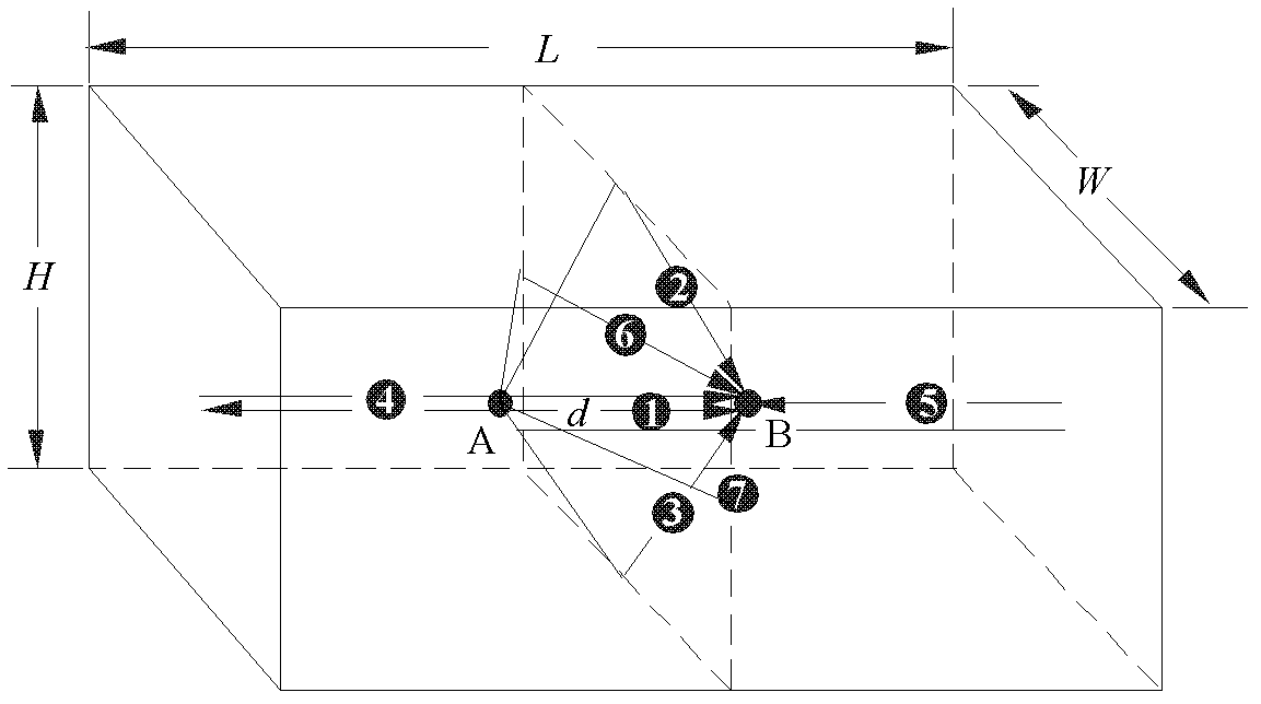
[0098] Embodiment: In order to facilitate the description of the influence of the boundary of the limited area on the free field condition, a model capable of describing the sound field in the acoustic medium of the limited area is established, such as figure 1 shown. Taking the rectangular hexahedron as an example, point A is the acoustic emitter, and point B is the acoustic receiver. If the influence of the secondary acoustic reflection on the boundary of the limited area is not considered, the acoustic receiver at point B will receive seven acoustic signals from different sound paths after the acoustic signal is radiated by the acoustic emitter at point A, respectively : The direct sound signal is represented by number 1 in the attached figure; the reflected sound signal from the upper boundary of the limited area is represented by the number 2 in the attached figure; t...


PUM


Abstract

The invention relates to a method for calibrating sound pressure in a low-frequency sound wave free field. The method comprises the following steps of: 1) arranging an emitting sensor and a receiving sensor on a calibration bracket in a finite area, wherein the emitting sensor emits a pulse signal with a certain parameter, and the receiving sensor acquires a received sound pressure signal; 2) changing an absolute position of the calibration bracket in a calibration area, retaining the emitting sensor and the receiving sensor at the original positions of the calibration bracket, keeping a relative position between the emitting sensor and the receiving sensor unchanged, and acquiring the received sound pressure signal by the receiving sensor; and 3) synchronously superposing the signals acquired twice, averaging the superposed signal, and thus obtaining a required sound pressure signal of the free field. The method has the advantages that: the method is easy and convenient to operate; influence of boundary reflection is not needed to be considered; the influence of a reflected signal on a through sound signal can be effectively suppressed at a low frequency band of the sound wave; the lower frequency limit of sound pressure calibration of the indoor free field is expanded; and the method is reliable.

Description

technical field [0001] The invention relates to a sound field signal processing technology, in particular to a low-frequency sound wave free-field sound pressure calibration method. Background technique [0002] 1. Free field calibration [0003] Free field is the abbreviation of free sound field, which refers to the sound field produced by the sound source in a homogeneous and isotropic infinite medium without reflected sound and scattered sound. In the acoustic calibration test, the most commonly used and most suitable sound field for the actual use environment is the free field. Due to the difference in sound velocity and density in different media, sound waves will be reflected and refracted at the interface of the media. Sometimes even if there are reflected sound and scattered sound, they have no effect on the original radiated sound field of the sound source in a certain area or within a certain time interval, and the sound field is also a free field. [0004] The ...

Claims


Application Information

Patent Timeline
Patent Type & Authority Applications(China)
IPC IPC(8): H04B17/00H04B11/00H04B17/309
Inventor 禹建费腾朱学文
Owner THE 715TH RES INST OF CHINA SHIPBUILDING IND CORP
Learn More