Dust catcher

A dust collector, the same technology, applied in chemical instruments and methods, separation of dispersed particles, use of liquid separation agent, etc., can solve the problems of poor gas passage, blockage of solid particles, complex structure, etc., and achieve simple structure, material saving, The effect of reducing investment

Active Publication Date: 2012-07-04
CHINA PETROLEUM & CHEM CORP +1
View PDF9 Cites 9 Cited by
  • Summary
  • Abstract
  • Description
  • Claims
  • Application Information

AI Technical Summary

Problems solved by technology

[0003] The purpose of the present invention is to provide a dust collector to solve the problem that the existing dust collector has a relatively

Method used


Image

  • Dust catcher
  • Dust catcher
  • Dust catcher

Examples


Embodiment

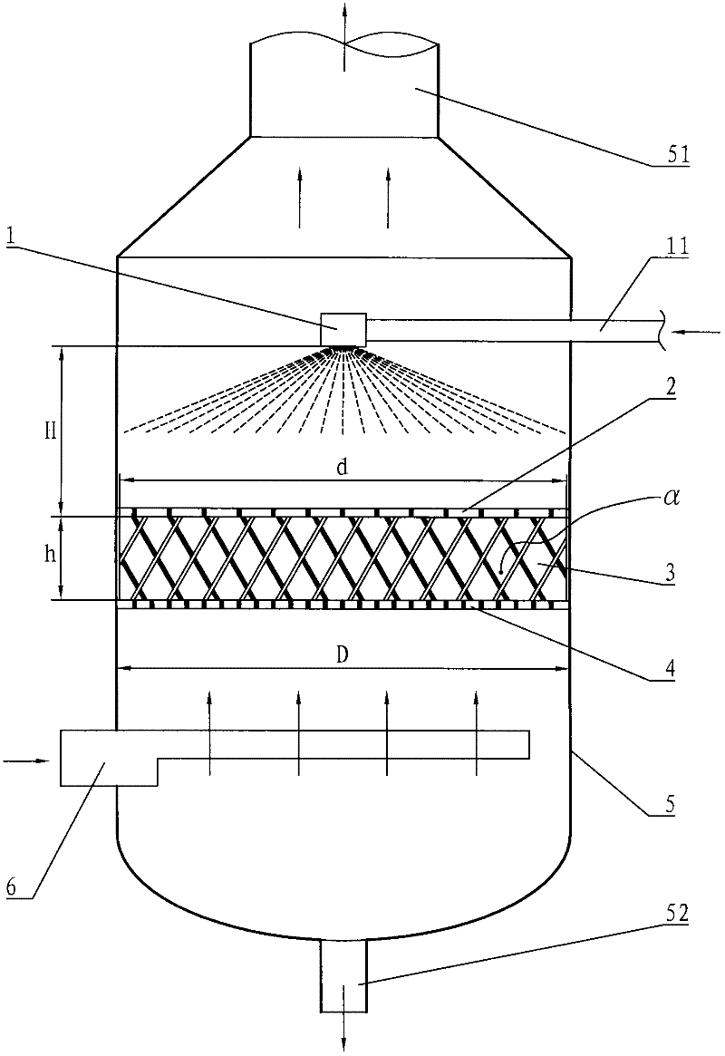
[0031] use figure 1 The shown stand-alone dust collector of the present invention was tested at normal temperature and pressure. Gas containing solid particles was simulated by air containing catalyst particles, the content of catalyst particles was 800 mg / m3. The catalyst is a petroleum processing fluidized catalytic cracking catalyst (spent catalyst), and the bulk density (compressed state) is 1 g / cubic centimeter. The proportion of particles with an equivalent diameter of less than 50 microns is 89.87w% (w% means weight percentage), and the proportion of particles with an equivalent diameter of more than 50 microns is 10.13w%. During operation, the superficial gas velocity is 6.56 m / s, and the liquid-gas ratio is 0.1 liter / cubic meter. The flow rate of the air containing catalyst particles entering the casing 5 from the gas distributor 6 is 26700 cubic meters per hour.

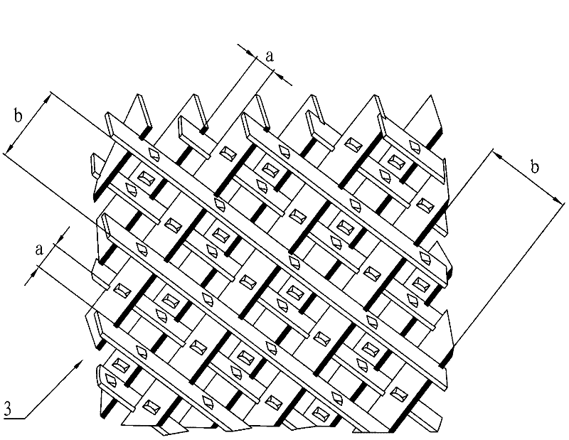
[0032] The grid filler 3 is disc-shaped, with a diameter d of 1.2 meters and a height h of 400 mm. I...


PUM

PropertyMeasurementUnit
Heightaaaaaaaaaa

Abstract

The invention discloses a dust catcher, which solves the problems of complex structure, gas obstruction caused by an active carbon filter screen and high possibility of blockage of solid granules in the conventional dust catcher. The dust catcher is provided with a grid packing (3), and a liquid sprayer (1) is arranged above the grid packing (3); the grid packing (3) is a packing layer with a three-dimensional gridding runner and consists of strip plates which are arranged in a row, and the strip plates are tilted with a horizontal plane; and the same rows of strip plates are parallel with each other, the inclination directions of the two adjacent rows of strip plates with the horizontal plane are opposite, and the two adjacent rows of strip plates are crossed mutually. The dust catcher is mainly used for dust removal in enterprises of petrochemical industry, pyroelectricity industry, steel industry and the like.

Description

technical field [0001] The present invention relates to a dust collector for removing solid particles from a gas. Background technique [0002] In petrochemical, thermal power, steel and other enterprises, various dust collectors are widely used to remove solid particles in gas (such as flue gas). Chinese patent CN2460218Y discloses a fire-smoke turbulent flow hybrid separation and filtration device, which is provided with a rectangular pipe connected to a cyclone separator. A liquid-gas jet secondary turbulent mixer and an atomizing nozzle are arranged in the rectangular pipe, and an atomizing nozzle of the cyclone separator is arranged obliquely above the inlet of the cyclone separator. The lower end of the cyclone separator is connected to the liquid storage tank, the upper end is provided with an activated carbon filter screen, and the top of the shrinking section of the cylindrical body is provided with an air outlet. The liquid-gas jet two-stage turbulent flow mixer ...

Claims


Application Information

Patent Timeline
IPC IPC(8): B01D47/14B01D53/78
Inventor 高有飞胡敏侯玉兰叶安道赵敏洁王长岭翁甲壮
Owner CHINA PETROLEUM & CHEM CORP
Why Eureka
Try Eureka