
System and method for forming disk part by performing two-stage atomizing and spraying

A spray forming and atomizing nozzle technology, which is applied in the field of atomization of molten metal and deposition of metal droplets, can solve the problems of large-diameter axisymmetric central hole parts with large difficulty, low gas density, and low momentum, etc., to achieve Reduce the densification process, reduce the average particle size, and improve the effect of microstructure

Inactive Publication Date: 2012-07-04
NORTHWESTERN POLYTECHNICAL UNIV
View PDF10 Cites 21 Cited by
  • Summary
  • Abstract
  • Description
  • Claims
  • Application Information

AI Technical Summary

Problems solved by technology

[0003] The traditional spray forming process represented by the Osprey mode uses inert gas to atomize molten metal, and its gas flow velocity is lower than the speed of sound. This forming method has the following disadvantages: (1) Due to the low gas density and low momentum, the atomization efficiency is very low. Low, the average particle size of the atomized droplets is large, and the size distribution range of the atomized droplets is wide; (2) Due to the limitations of the traditional spray forming process itself, it is very difficult to form large-diameter axisymmetric center hole parts; (3) There are inevitably pores in the microstructure of spray-formed alloys, about 3% to 6%
Pores, as a structural defect, split the continuity of the matrix, which will reduce the mechanical properties of the material, and the densification and plastic processing of large-diameter thin-walled pipe fittings are not easy to achieve

Method used


Image

  • System and method for forming disk part by performing two-stage atomizing and spraying
  • System and method for forming disk part by performing two-stage atomizing and spraying

Examples


Embodiment Construction

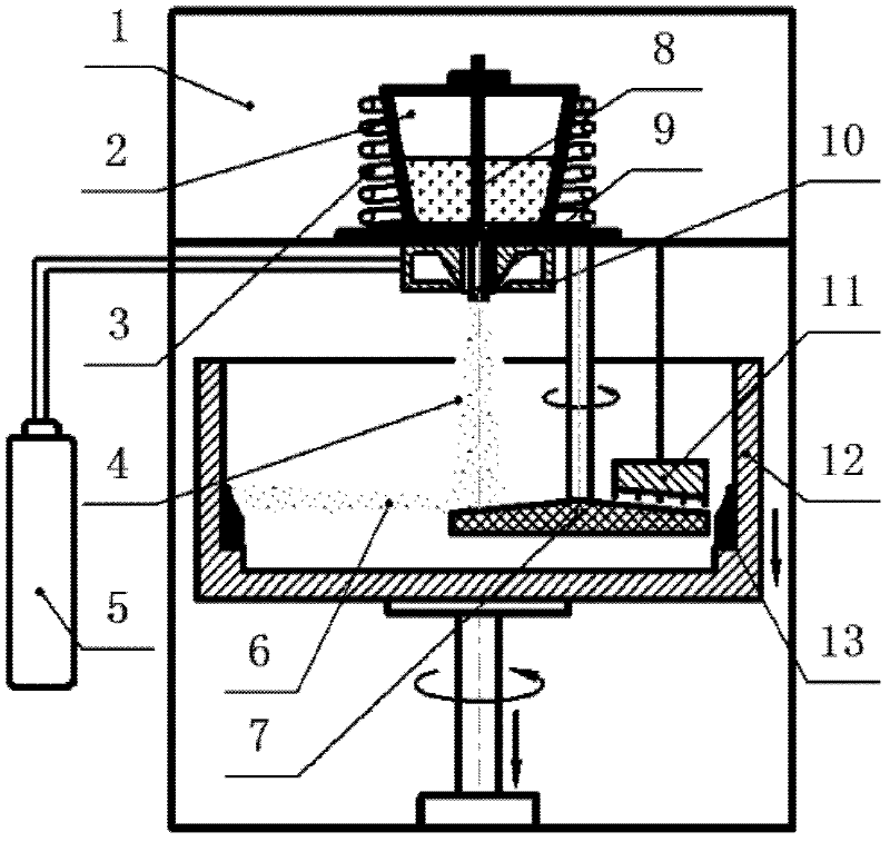
[0019] Now in conjunction with embodiment, accompanying drawing, the present invention will be further described:

[0020] The system of this embodiment comprises a vacuum chamber 1 with an internal size of 2 m high and a diameter of 1.2 m, a crucible 2 with a height of 0.2 m and a diameter of 0.18 m, a heating coil 3, a gas storage cylinder 5, a mechanical ejection disc 7 with a diameter of 0.3 m, and Through rod 8, catheter tube 9, high-pressure gas atomization nozzle 10, cooling device 11 and ring mold 12 with a diameter of 0.8m; wherein crucible 2, heating coil 3, stop rod 8, catheter tube 9 and atomization nozzle 10 Located in the upper part of the vacuum chamber 1, the crucible 2 is located in the center of the upper part of the vacuum tank 1, and is connected to the catheter 9 through the threaded hole at the bottom, and the stop rod 8 is connected to the catheter 9 and the bottom of the crucible 2 The threaded through holes are coaxial, and can move up and down along i...


PUM


Abstract

The invention provides a system and method for forming a disk part by performing two-stage atomizing and spraying. The method comprises the following steps of: performing first-stage atomizing: spraying high-speed inert gas out of an atomizing nozzle for atomizing molten metal to form an atomizing cone; performing second-stage atomizing: colliding metal molten drops in the atomizing cone with a throw-away disk in a flying process, and further refining the molten drops at a high relative speed under the colliding and centrifuging actions of the throw-away disk which rotates at a high speed and the molten drops; and after two-stage atomizing is completed, making the metal molten drops fly towards a receiving mold at a very high speed, performing quick condensation in the process, and depositing and forming on the receiving mold finally, wherein the annular mold rotates at a high speed, and the received semi-solid liquid drops occupy pores generated by depositing under the action of centrifugal force, so that the porosity of a depositing blank is lowered. The annular mold can move up and down along an axial direction during high-speed rotation, and the wall thickness and axial length of a formed piece can be controlled by adjusting axial feeding speed and total feeding amount.

Description

technical field [0001] The invention relates to a method for preparing discs, round tubes, rings and other parts with large-diameter axisymmetric central holes by using two-stage atomization spray forming technology, and particularly relates to the atomization method of molten metal and the deposition method of metal droplets. Background technique [0002] Spray forming technology is an advanced forming technology developed in the past 30 years, which uses rapid solidification method to directly prepare metal material blanks or semi-finished products. The process is to atomize molten metal into tiny liquid droplets, and then driven by high-speed airflow, the tiny droplets are directly sprayed on a cooler receiver to form parts. The material prepared by spray forming has the following excellent characteristics: (1) fine grain, uniform composition, high supersaturation of alloying elements, and no macro-segregation; (2) low oxygen content, and the atomized molten droplet stays...

Claims


Application Information

Patent Timeline
IPC IPC(8): B22F3/115
Inventor 司朝润王俊彪张贤杰李玉军曹小宝
Owner NORTHWESTERN POLYTECHNICAL UNIV
Features
  • Generate Ideas
  • Intellectual Property
  • Life Sciences
  • Materials
  • Tech Scout
  • Unparalleled Data Quality
  • Higher Quality Content
  • 60% Fewer Hallucinations
Learn More