Ram flexibility compensation mechanism of heavy numerical control floor type milling and boring machine

A compensation mechanism and floor-standing technology, applied in other manufacturing equipment/tools, manufacturing tools, etc., can solve problems such as deflection and deformation

Inactive Publication Date: 2012-07-04
ZHONGJIE MACHINE TOOL
View PDF3 Cites 9 Cited by
  • Summary
  • Abstract
  • Description
  • Claims
  • Application Information

AI Technical Summary

Problems solved by technology

[0005] The purpose of the present invention is to provide a ram deflection compensation mechanism for a heavy-duty CNC floor-type milling and boring machine. An external load is applied to the ram to produce a deformation that is equal in size and opposite to

Method used


Image

  • Ram flexibility compensation mechanism of heavy numerical control floor type milling and boring machine
  • Ram flexibility compensation mechanism of heavy numerical control floor type milling and boring machine
  • Ram flexibility compensation mechanism of heavy numerical control floor type milling and boring machine

Examples


Embodiment Construction

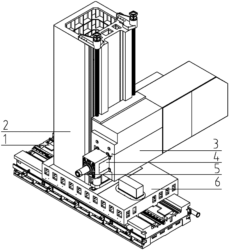
[0014] The structure of the existing CNC floor-type milling and boring machine is shown in figure 1 , the vertical column 2 is installed on the bottom bed 1 and the sliding seat 6, the headstock 3 is hung on the side elevation of the column 2, and the ram 4 in the horizontal state plays a role in connecting the headstock 3 and the main shaft in the CNC floor milling and boring machine 5 role. The ram 4 overall shape is a cuboid, and the four sides in the axial direction are guide rail surfaces, and a milling shaft and a boring shaft are installed inside. The ram and the boring shaft can move forward and backward. When the ram and the boring shaft protrude for a long time, the ram will bend and deform.

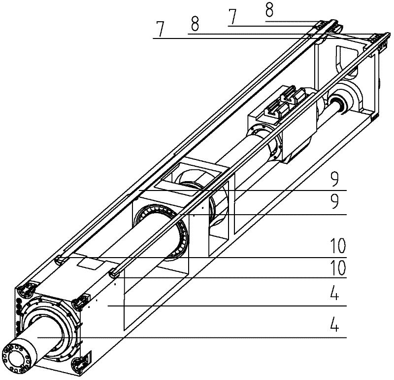
[0015] The ram deflection compensation mechanism of this heavy-duty CNC floor-type milling and boring machine of this design is characterized in that two tie rods 9 are installed at the upper two corners inside the ram 4 with a square cross-section, and the installation arrang...


PUM


Abstract

The invention discloses a ram flexibility compensation mechanism of a heavy numerical control floor type milling and boring machine. Flexible deformation is compensated by using a pull rod. The ram flexibility compensation mechanism is characterized in that: two elongated pull rods are arranged at two corners above the internal space of a ram; a hydraulic oil cylinder for providing pull force is fixed at the rear end of the ram; after being serially assembled by the pull rods, the ram, the pull rods and the oil cylinder are fixed by using a sleeve screw cap at the rear end of the hydraulic oil cylinder; a sleeve is designed between the pull rods and a piston for connecting the piston and the pull rods; the sleeve is integrally fixed to the pull rods at the rear ends of the pull rods through screw caps; no relative motion exists between the pull rods and the piston; baffle rings are embedded between the sleeve and the piston in pair to fix the sleeve and the piston; and the pull rods are driven by the piston to produce backward pull force by the cam, so that bending deformation caused by gravity of the cam is compensated. According to the designed sleeve, the strict process of machining an annular groove is saved, and a supercharging oil cylinder meets the requirement of small size. According to the design, automatic compensation for the motion straightness of the cam can be realized, meanwhile, motion straightness of the main shaft can also be obviously improved.

Description

technical field [0001] The invention relates to mechanical manufacturing equipment, in particular to a ram deflection compensation mechanism for a heavy-duty numerical control floor-type milling and boring machine. technical background [0002] In recent years, with the rapid development of industries such as energy, metallurgy, and construction machinery, many key components in these industries tend to be larger and more complex, and the precision required for each processing surface is also very high, which requires metal cutting The focus of machine tool development is mainly concentrated on heavy-duty machine tools with high torque, large stroke and high precision. [0003] The CNC floor milling and boring machine is a general-purpose machine used for machining large-scale parts. It is widely used in industries such as energy, metallurgy, and engineering machinery. The pillow constitutes the cantilevered moving part. Heavy-duty CNC floor-type milling and boring machine...

Claims


Application Information

Patent Timeline
IPC IPC(8): B23Q23/00
Inventor 孔令友贺鑫元孙玉民刘宗际姜成伟王建利姜嘉炜高亮
Owner ZHONGJIE MACHINE TOOL
Why Eureka
Try Eureka