Electric power assisting device for automobile brake system

An automobile braking system and electric power assist technology, applied in the field of vehicles, can solve the problems of reducing the flexibility and stability of braking, affecting the normal operation of electric control and accessories, and complex conditions of automobile power assist devices, so as to ensure the accuracy and function The effect of uniform force and improved work efficiency

Active Publication Date: 2012-07-04
ZHEJIANG GEELY AUTOMOBILE RES INST CO LTD +1
View PDF4 Cites 9 Cited by
  • Summary
  • Abstract
  • Description
  • Claims
  • Application Information

AI Technical Summary

Problems solved by technology

Although the brake booster has the advantages of reduced space occupation and compact structure, it also has certain defects.
1. Although permanent magnets are used, the conditions in the car power booster are relatively complicated, so the magnetism of the permanent magnets will gradually fade away; thus gradually reducing the power boosting effect
2. A permanent magnet is installed in the car booster, and the magnet's strong magnetism produces electromagnetic interference, which will affect the normal operation of the electronic control and accessories.
3. The car often needs to brake when driving, so the return spring is stretched back and forth, which is easy to cause mechanical fatigue, resulting in a decrease in the elasticity of the return spring, which in turn reduces the boosting effect gradually
4. When braking, the spring is compressed, and this structure also causes the force applied by the driver to increase with the increase of the braking stroke, thereby reducing the flexibility and stability of braking

Method used


Image

  • Electric power assisting device for automobile brake system
  • Electric power assisting device for automobile brake system
  • Electric power assisting device for automobile brake system

Examples


Embodiment 1

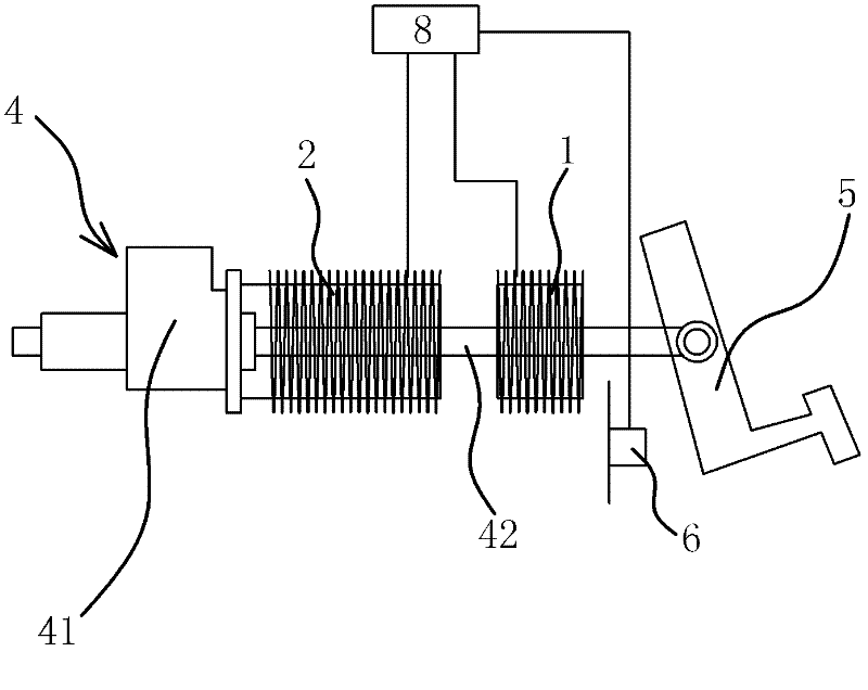
[0035] Such as figure 1 As shown, the electric booster of the automobile braking system is arranged between the brake pedal 5 and the brake master cylinder 4, and it includes an electromagnetic coil one 1, an electromagnetic coil two 2, an electronic induction unit and an ECU8.

[0036] Such as figure 1 As shown, specifically, the brake master cylinder 4 includes a cylinder body 41 fixed on the vehicle body and a push rod 42 pierced on the cylinder body 41 , the free end of the push rod 42 is hinged to the brake pedal 5 .

[0037]The electromagnetic coil one 1 is sheathed on the push rod 42 , and the electromagnetic coil one 1 is fixedly connected with the push rod 42 . The second electromagnetic coil 2 is located on one side of the first electromagnetic coil 1 , and one pole of the second electromagnetic coil 2 is opposite to one pole of the first electromagnetic coil 1 . The second electromagnetic coil 2 is fixed on the fixing part of the automobile, and the fixing part is...

Embodiment 2

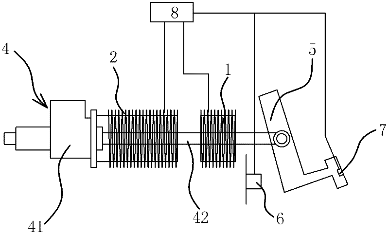
[0044] The structure and principle of this embodiment are basically the same as that of Embodiment 1, the difference is that: figure 2 As shown, the electronic sensing unit also includes a pressure sensor 7 fixed on the tread of the brake pedal 5 . The pressure applied to the tread of the brake pedal 5 by the driver is completely different when performing increased braking and canceling the braking. If there is a reduction, the above-mentioned pressure changes can be sensed by the pressure sensor 7 and generate corresponding signals to be transmitted to the ECU 8 . Simultaneously using the distance sensor 6 and the pressure sensor 7 to sense the actions of the driver can ensure the accuracy, stability and sensitivity of the sensing.

Embodiment 3

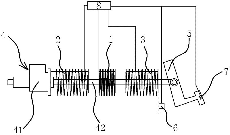
[0046] The structure and principle of the present embodiment are basically the same as those of the second embodiment, the difference is that: image 3 As shown, the electric booster also includes an electromagnetic coil three 3, one pole of the electromagnetic coil three 3 is opposite to the other pole of the electromagnetic coil one 1; The above-mentioned ECU 8 that can control the energization state of the electromagnetic coil three and three coils according to the action state of the brake pedal 5 sensed by the electronic trigger control mechanism is electrically connected. When the electromagnetic coil one 1, the electromagnetic coil two 2 and the electromagnetic coil three 3 are powered The absorption-repulsion state between one 1 and electromagnetic coil two 2 is opposite to the absorption-repulsion state between electromagnetic coil one 1 and electromagnetic coil three 3 .

[0047] Setting the electromagnetic coil three 3 can increase the force that the electromagnetic...


PUM


Abstract

The invention provides an electric power assisting device for an automobile brake system and belongs to the technical field of vehicles. The electric power assisting device solves the technical problems of poor brake flexibility, poor stability and the like of the existing electromagnetic power assisting device. The electric power assisting device for the automobile brake system comprises a first electromagnetic coil and a second electromagnetic coil, wherein the first electromagnetic coil is fixedly arranged on a push rod, the second electromagnetic coil is fixedly arranged on an automobile fixing element, one electrode of the second electromagnetic coil corresponds to one electrode of the first electromagnetic coil, an electronic sensing unit capable of sensing the action state of a brake pedal is also arranged on the automobile fixing element, the electronic sensing unit is connected with an electronic control unit (ECU), and the ECU is electrically connected with the coil of the first electromagnetic coil and the coil of the second electromagnetic coil and can control the electrification states of the coil of the first electromagnetic coil and the coil of the second electromagnetic coil according to the brake pedal action state sensed by an electronic triggering control mechanism. The electric power assisting device ensures that the force exerted on the pedal by drivers is uniform regardless of the length of the brake stroke, and simultaneously, the electric power assisting device has the advantages that the controllability is high, the brake power assisting effect is stable, and the like.

Description

technical field [0001] The invention belongs to the technical field of vehicles, and relates to a new energy vehicle, in particular to an electric booster device for a vehicle braking system. Background technique [0002] Automobile refers to a vehicle driven by its own equipment; generally has four or more wheels, and does not rely on rails or wires to drive on land. A car includes components such as the body, drive system, and brake system. [0003] At present, traditional cars are generally driven by internal combustion engines, and petroleum is a non-renewable energy source, and burning petroleum will also pollute the environment. In order to solve the energy crisis and environmental pollution problems, the development of new energy-driven vehicles has become the general trend. [0004] There is a vacuum booster device in the braking system of the vehicle driven by the internal combustion engine, and the vacuum source of the vacuum booster device comes from the intake ...

Claims


Application Information

Patent Timeline
Patent Type & Authority Applications(China)
IPC IPC(8): B60T13/74
Inventor 王汝成金启前由毅吴成明赵福全
Owner ZHEJIANG GEELY AUTOMOBILE RES INST CO LTD
Why Eureka
Try Eureka