Composite multi-frequency-band vibration isolation trench for building

A composite, multi-band technology, used in buildings, building components, protection devices, etc., to achieve the effects of comprehensive performance, simple structure and reasonable combination of components

Inactive Publication Date: 2012-07-04
BEIJING UNIV OF TECH
View PDF3 Cites 18 Cited by
  • Summary
  • Abstract
  • Description
  • Claims
  • Application Information

AI Technical Summary

Problems solved by technology

At present, there is still a lack of vibration isolation measures that have a good vibration reduction effect on all frequency bands of high, medium and low

Method used


Image

  • Composite multi-frequency-band vibration isolation trench for building
  • Composite multi-frequency-band vibration isolation trench for building
  • Composite multi-frequency-band vibration isolation trench for building

Examples


Embodiment 1

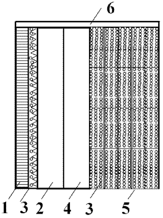
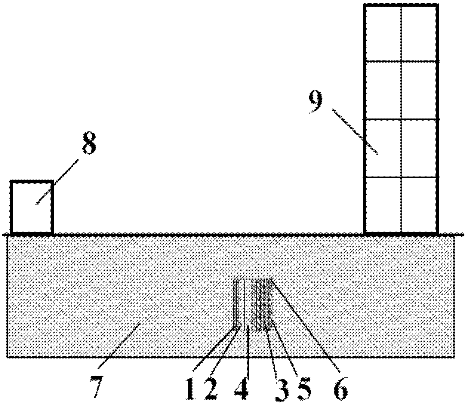
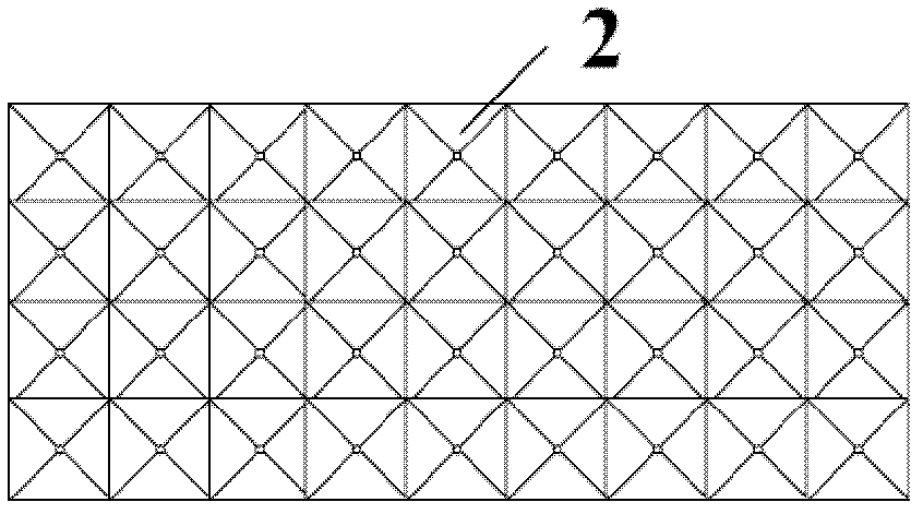
[0032] Such as figure 2 As shown, a 20-storey high-rise building is located 50m away from the main line of the urban light rail transit, and is seriously affected by the environmental vibration of the traffic system. -3 m / s 2 , the amplitude of vibration acceleration on the top floor of the building is 1.41×10 -2 m / s 2 . In order to reduce the vibration amplitude, the composite multi-band vibration isolation ditch for buildings of the present invention is used for vibration reduction and isolation. First, determine the specific location and size of the excavated vibration isolation ditch on the open space on the side of the high-rise building facing the vibration source. The vibration isolation ditch is 10m away from the outer surface of the building, with a width of 5m and a height of 6m. The depth from the top to the surface is 5m, and the total longitudinal length is 60m. Secondly, determine the detail size of each part of the vibration isolation trench. Among them, ...

Embodiment 2

[0034] Such as figure 2 As shown, a certain ancient building is located 200m away from the main line of the urban subway, which is seriously affected by the environmental vibration of the traffic system, which is not conducive to the protection of cultural relics. When the train passes by, the surface vibration acceleration amplitude of the ancient building is 3.1×10 -3 m / s 2 , the vibration acceleration amplitude of the indoor floor of the ancient building is 8.82×10 -3 m / s 2 . In order to reduce the vibration amplitude, the composite multi-band vibration isolation ditch for buildings of the present invention is used for vibration reduction and isolation. First, determine the specific location and size of the excavated vibration isolation ditch in the open space around the ancient building. The vibration isolation ditch is 25m away from the outer surface of the building, with a width of 4m and a height of 5m. The depth from the top to the surface is 5m. The plane is cir...


PUM


Abstract

The invention relates to a composite multi-frequency-band vibration isolation trench for a building, belonging to the technical fields of civil engineering and mechanical engineering. The composite multi-frequency-band vibration isolation trench comprises a perforated plate, an irregular plate, fillers, a hollow trench and a wave drag block, and is at least arranged under the earth surface on one side of the building, which faces a vibration source; the perforated plate, the irregular plate, the hollow trench and the wave drag block are sequentially connected with one another according to a direction from the vibration source to the building, and the heights and the widths of the perforated plate, the irregular plate, the hollow trench and the wave drag block are ensured to be consistent; one side of the irregular plate, which faces the vibration source, has a convex-concavo irregular structure, and the other side of the irregular plate is planar; and the fillers are filled in the irregular plate and the wave drag block.

Description

technical field [0001] The invention relates to a composite multi-frequency band vibration isolation ditch for buildings, which belongs to the technical fields of civil engineering and mechanical engineering. Background technique [0002] In recent years, urban infrastructure projects such as high-rise and long-span buildings, large-scale overpasses and tunnel projects, subway projects, and large-scale hydropower projects have been successively constructed in large cities, forming a representative group of modern civil engineering (structure) buildings and a representative group of civil engineering structures. Stereo engineering system. In this complex system, the transportation system represented by subway, urban high-speed rail and light rail will cause vibrations in the ground and surrounding buildings, seriously affecting people's daily activities and the use of laboratory precision instruments. Therefore, it is extremely necessary to carry out research on vibration is...

Claims


Application Information

Patent Timeline
Patent Type & Authority Applications(China)
IPC IPC(8): E02D31/08E04B1/98
Inventor 何浩祥闫维明周宏宇葛腾飞
Owner BEIJING UNIV OF TECH
Why Eureka
Try Eureka