Assembled half-exposed framework high-pressure seal ring

A high-pressure sealing ring, half-exposed skeleton technology, applied in the direction of engine sealing, engine components, mechanical equipment, etc., can solve problems such as poor pressure resistance and extrusion resistance, heat generation, and increase installation space, and achieve Stable anti-extrusion ability, good friction and lubricating properties, and the effect of lowering the ambient temperature

Active Publication Date: 2012-07-04
重庆杜马斯克科技有限公司 +2
View PDF7 Cites 12 Cited by
  • Summary
  • Abstract
  • Description
  • Claims
  • Application Information

AI Technical Summary

Problems solved by technology

[0003] The earlier high-pressure sealing ring (see attached figure 1 As shown), it is composed of a metal skeleton, a spring, a rubber body with a sealing lip, etc. The metal skeleton and the rubber body are bonded as a whole by vulcanization using a mold. The main problems of products with this structure are as follows: In order to improve the sealing For high pressure resistance, the usual measure is to shorten the length of the sealing waist (L1 is shortened to L2 in the figure), increase the thickness T of the waist, or increase the hardness of the rubber material. However, after these measures are implemented, the pressure resistance of the sealing ring has been improved to a certain extent. , but the problem is that the eccentric adaptability of the seal ring is significantly reduced, and the friction torque of the seal ring is increased; in order to improve the anti-extrusion ability of the seal, a baffle needs to be added on the side of the seal and non-seal, which makes the assembly change. complicated
[0005] 1. Since the material of the general pressure ring is low-strength plastic (such as nylon material, polyethylene, etc.), the strength and adaptable temperature range are not high and the wear resistance is poor
When the hydraulic pressure reaches the pressure-bearing ring of the plastic, the oil seal will leak due to the damage of the pressure-bearing ring. The test proves that the oil seal with this structure is at a pressure of about 20 MPa, and the pressure-bearing ring will be damaged and leak.
[0006] 2. When the sealing ring is working, because the plastic ring is tightly attached to the surface of the shaft under the action of radial force, the plastic bearing ring will always have dynamic friction with the shaft surface. In view of the large friction pair between plastic and metal, it will continue to produce Heat, which will increase the value of the oil seal lip, thereby accelerating the damage failure rate and aging rate of the lip
This causes the sealing lip to be squeezed out of the gap between the plastic pressure ring and the shaft
[0008] 4. Due to the low strength of the plastic pressure bearing ring, in order to avoid the direct action of the hydraulic pressure on the plastic pressure bearing ring, the oil seal with this structure can only shorten the waist length L of the seal, resulting in poor tracking of the eccentricity of the sealing lip. , increasing the possibility of sealing medium leakage
[0009] 5. As shown in attached drawing 2-2, since the plastic support ring of the seal is usually directly installed from the outer end face of the seal, if the proper axial fixation is not made during installation, once the seal is under pressure, the plastic support ring will will be flushed out and the sealed waist will be squeezed out
[0012] 1. In order to prevent the shaft from being damaged and heat generated due to the contact between the metal pressure ring and the shaft, there is a large gap between the metal pressure ring and the shaft, so it is very easy for the rubber to be squeezed out along the gap and damaged under high pressure, so The pressure resistance and extrusion resistance of this structural oil seal are poor
[0013] 2. When assembling the seal of this structure, since the metal pressure bearing ring needs to be put into the shell first and then the oil seal is pressed, the assembly is complicated, and the production cost and installation space are increased at the same time.

Method used


Image

  • Assembled half-exposed framework high-pressure seal ring
  • Assembled half-exposed framework high-pressure seal ring
  • Assembled half-exposed framework high-pressure seal ring

Examples


Embodiment Construction

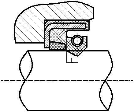
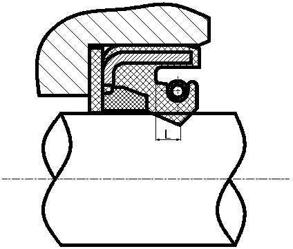
[0046] Figure 4 —13 is the structure diagram of the present invention, as shown in the figure: the assembled semi-exposed frame high-pressure sealing ring includes an annular rubber body with a sealing lip 3, a metal frame 6, a semi-exposed frame 5, and a composite pressure ring 4 and spring 2. The metal skeleton 6 and the rubber body 1 are thermally vulcanized and bonded as a whole; the annular rubber body 1 is provided with a sealing lip 3 with a certain amount of interference between the matching shaft, and the sealing lip 3 is molded by a mold at a time form. The composite bearing pressure ring 4 is assembled behind the sealing lip 3 after the metal frame and rubber are vulcanized as a whole; the half exposed frame 5 is finally assembled with the rubber body 1 and the composite pressure ring 4 as a whole. The extension spring 2 is connected end to end and installed in the spring groove behind the sealing lip 3. The extension spring 2 exerts a stable radial pressure on the...


PUM


Abstract

The invention discloses an assembled half-exposed framework high-pressure seal ring, which not only can seal in a rotating way, but also can seal in a reciprocating way. The seal ring includes a rubber body with a sealing lip, a metal framework vulcanized in the rubber, and a half-exposed framework, a pressure bearing ring taking a metal or non-metal composite material and a spring that are assembled on the rubber body. The half-exposed framework, the composite material pressure bearing ring and the rubber body of the seal ring are designed in an assembling way; and the composite material pressure bearing ring is arranged between the half-exposed framework and the sealing lip, and the pressure bearing ring bears a large amount of working pressure. The assembled half-exposed framework high-pressure seal ring has extremely high high-pressure resistance, outstanding and stable extrusion resistance, excellent heat dissipation and friction lubricating property, good eccentricity adaptability, extremely long service life, simple process, and efficient and stable machining.

Description

technical field [0001] The invention relates to an assembled high-pressure sealing ring with a semi-exposed skeleton. It is a high-pressure seal suitable for sealing between reciprocating shafts, rotating shafts, pistons and cylinders. Background technique [0002] Hydraulic systems are widely used in mechanical equipment and automation devices, such as construction machinery, mining machinery, agricultural machinery, chemical machinery, ships and automobile hydraulic power steering devices, etc. The internal working pressure of the hydraulic system is often between tens to hundreds of atmospheres, and its operation and running reliability largely depend on the seals in the system. Therefore, high-pressure sealing rings with good sealing performance are used in hydraulic systems. role is extremely important. [0003] The earlier high-pressure sealing ring (see attached figure 1 As shown), it is composed of a metal skeleton, a spring, a rubber body with a sealing lip, etc....

Claims


Application Information

Patent Timeline
Patent Type & Authority Applications(China)
IPC IPC(8): F16J15/32F16J15/3208F16J15/324F16J15/3252
Inventor 杜长春
Owner 重庆杜马斯克科技有限公司
Why Eureka
Try Eureka