Tin melting furnace

A technology for melting tin and furnace body, applied in furnaces, crucible furnaces, furnace types, etc., can solve the problems of low temperature control accuracy, unstable welding quality, inaccurate temperature values, etc., to achieve easy maintenance, improve welding quality, increase Effect of heat dissipation area

Active Publication Date: 2012-07-04
TIANJIN BINHAI ELECTRICAL EQUIP
View PDF8 Cites 5 Cited by
  • Summary
  • Abstract
  • Description
  • Claims
  • Application Information

AI Technical Summary

Problems solved by technology

Among them, the tin melting tank of the tin melting furnace is used to melt the solder material, so as to dip solder the printed circuit board or enameled wire containing electronic components, or to tin the pins of electronic components. The tin melting tank of the tin furnace is made of titanium alloy, stainless steel or other metal materials, with a flat bottom and a heating device placed below it. The inner surface of the tin melting tank near the heating element has a small heat dissipation area, low heating efficiency, and high energy consumption costs; The temperature sensor is placed below the bottom, and the detection position is far away from the inner cavity of the tin melting tank. The detected temperature value is inaccurate, and the temperature control accuracy is low, which makes the welding quality unstable; The chemical reaction of solder leads to corrosion damage. Generally, the service life of metal melting tanks is relatively low. In some assembly lines, often due to frequent breakage of tin melting furnaces, a large number of tin melting furnaces need to be replaced and repaired, resulting in high production costs and long maintenance hours. , especially some tin melting tanks are made of titanium alloy, which has higher maintenance costs; the existing tin melting furnaces use mechanical potentiometers to adjust and control the temperature, and the control accuracy is low, making the welding quality unstable

Method used


Image

  • Tin melting furnace
  • Tin melting furnace
  • Tin melting furnace

Examples


Embodiment Construction

[0023] In order to further understand the invention content, characteristics and effects of the present invention, the following examples are given, and detailed descriptions are as follows in conjunction with the accompanying drawings:

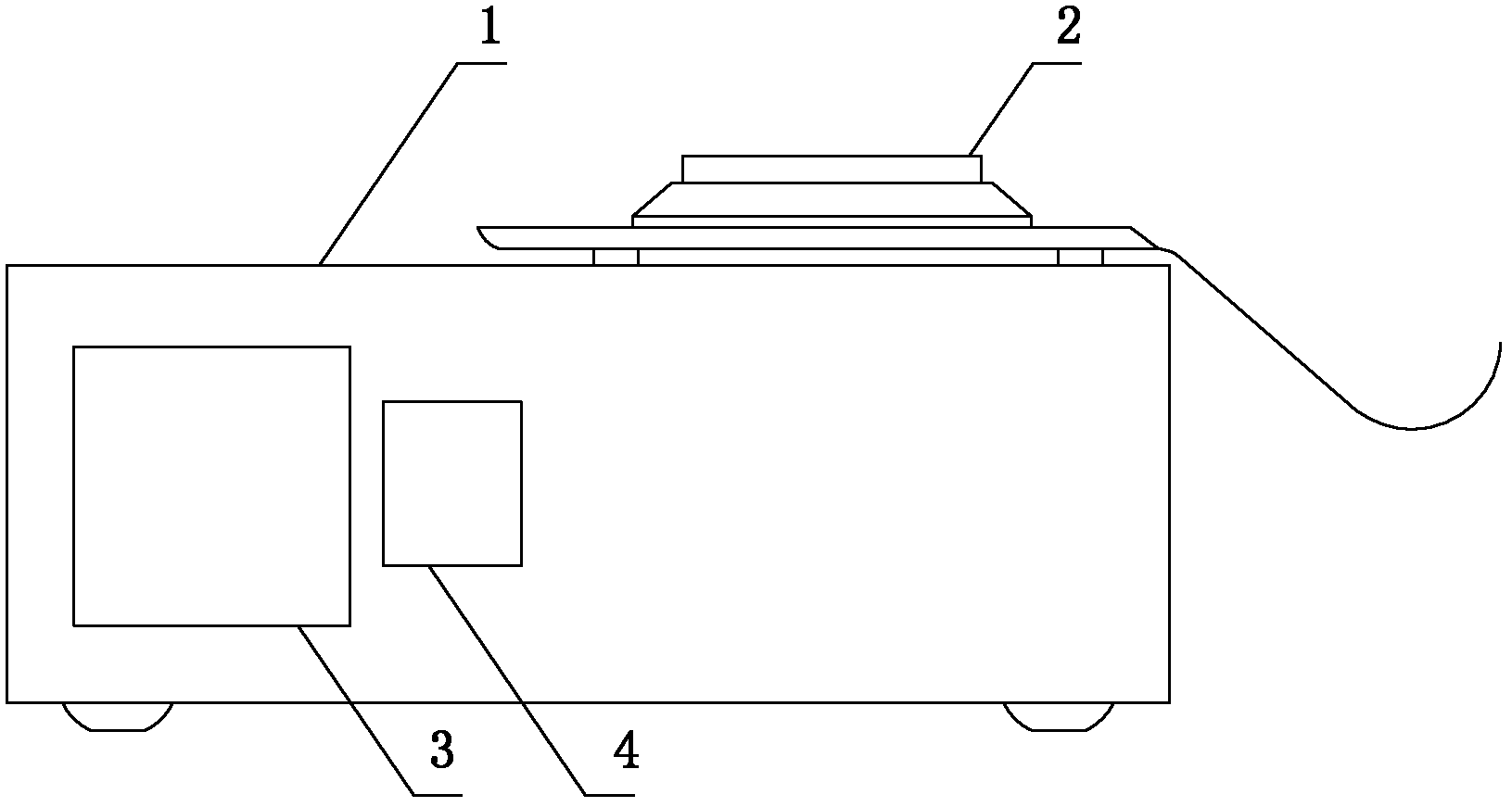
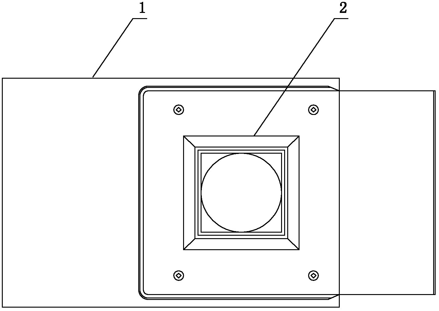
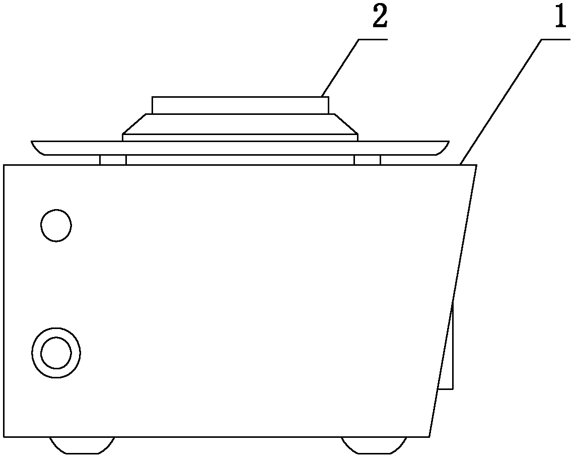
[0024] See Figure 1 to Figure 6 , a tin-melting furnace, comprising a furnace body 1, a tin-melting tank 2 arranged in the furnace body, a heating pipe, a temperature sensor and a temperature control circuit, the tin-melting tank 2 is a ceramic tin-melting tank, and the ceramic tin-melting tank The tank can be a 95 porcelain melting tin tank; the bottom of the tin melting tank 2 is horizontally provided with a plurality of side-by-side through holes 5, one of the through holes 5 is the hole for placing the temperature sensor, and the other through holes 5 are The heating tube placement hole, the number of the through holes 5 can be an odd number, and the central through hole 5 can be the temperature sensor placement hole; the bottom inner su...


PUM

PropertyMeasurementUnit
Wall thicknessaaaaaaaaaa

Abstract

The invention discloses a tin melting furnace which comprises a furnace body, a tin melting groove arranged in the furnace body, heating pipes, a temperature sensor and a temperature control circuit, wherein the tin melting groove is a ceramic tin melting groove, the bottom of the tin melting groove is provided with a plurality of in-parallel through holes along the horizontal direction, one of the through holes is a temperature sensor installing hole, the other through holes are heating pipe installing holes, and the inner surface at the bottom of the tin melting groove is provided with an arc lug boss corresponding to the axis of the through holes. According to the tin melting furnace, the welding quality can be improved, the production cost can be reduced, and the tin melting furnace is applicable to tin melting working procedures of various electronic product manufacturing industry and electrical product manufacturing industry, in particular to tin enameling working procedures of soldering lug, pin, connector assembly, cable head and the like of an electronic component.

Description

technical field [0001] The invention relates to a tin melting device, in particular to a tin melting furnace. Background technique [0002] At present, tin melting furnaces are widely used in various electronic and electrical product manufacturing industries. In terms of lead-free soldering process for small and medium-sized plug-in circuit boards, their work efficiency is dozens to hundreds of times higher than manual soldering. The operation is simple and the quality of solder joints is excellent. The appearance is consistent and stable, and it is especially widely used in tinning processes such as solder lugs, pins, connectors, and cable heads of electrical components. There is no dead spot in welding and reliable performance. Among them, the tin melting tank of the tin melting furnace is used to melt the solder material, so as to dip solder the printed circuit board or enameled wire containing electronic components, or to tin the pins of electronic components. The tin m...

Claims


Application Information

Patent Timeline
IPC IPC(8): F27B14/06F27B14/08F27B14/14F27B14/20
Inventor 刘巨胜李金花
Owner TIANJIN BINHAI ELECTRICAL EQUIP
Why Eureka
Try Eureka