Coil of optical fiber current sensor and optical fiber current sensor

A sensor coil, optical fiber current technology, applied in the direction of measuring current/voltage, voltage/current isolation, instruments, etc., can solve the problems of crosstalk between two orthogonal modes, affecting measurement accuracy, weakening stability, etc., and achieve strong anti-electromagnetic interference ability , Improve the stability of the zero bias and the effect of improving the measurement accuracy

Active Publication Date: 2012-07-04
XIAN SINO HUAXIN MEASUREMENT & CONTROL
View PDF8 Cites 9 Cited by
  • Summary
  • Abstract
  • Description
  • Claims
  • Application Information

AI Technical Summary

Problems solved by technology

The main problems that limit the practicality of fiber optic current sensors are: the Sagnac phase error caused by vibration or rotation, the phase error caused by the residual linear birefringence in the fiber when the temperature changes, etc.
This phase error and the Faraday phase shift together affect the output light intensity detected by the detector, thus causing errors in the measurement results, and finally causing errors in the calculated current to be measured, and the zero deviation of the sensor output is large
At the same time, a dual-axis modulator is required for phase modulation, which increases the complexity of the system and weakens the stability
And in the modulation process, it will cause crosstalk between two orthogonal modes, which will affect the measurement accuracy
[0008] Therefore, based on these technical defects, these current sensors cannot meet the actual needs at present, which limits their wide application in engineering.

Method used


Image

  • Coil of optical fiber current sensor and optical fiber current sensor
  • Coil of optical fiber current sensor and optical fiber current sensor
  • Coil of optical fiber current sensor and optical fiber current sensor

Examples


Embodiment Construction

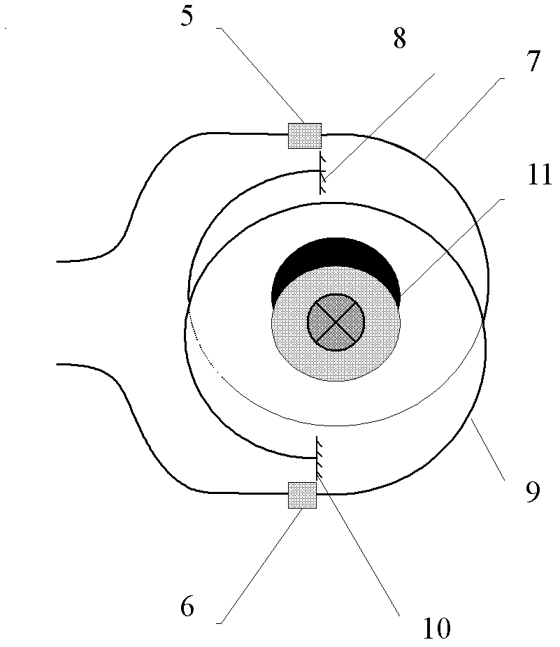
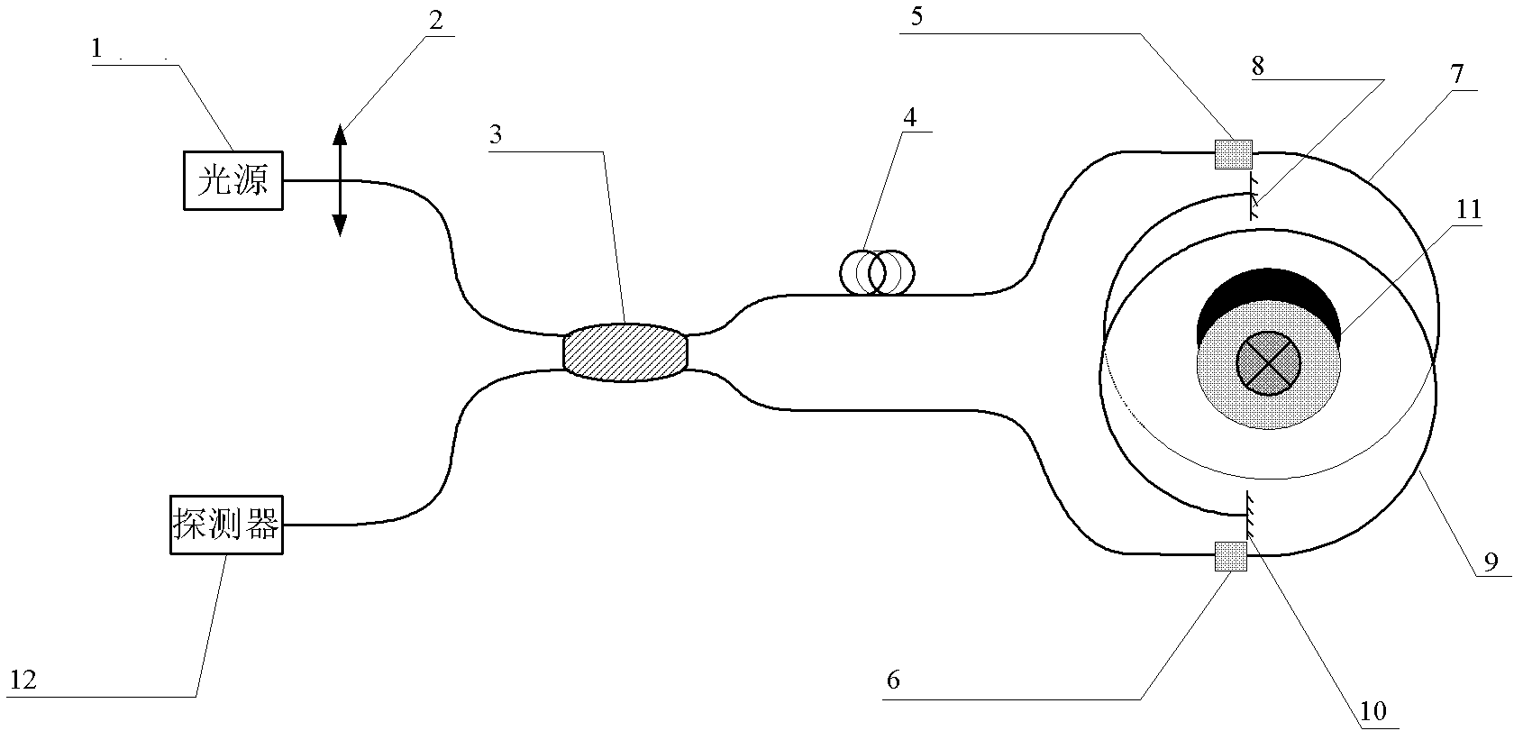
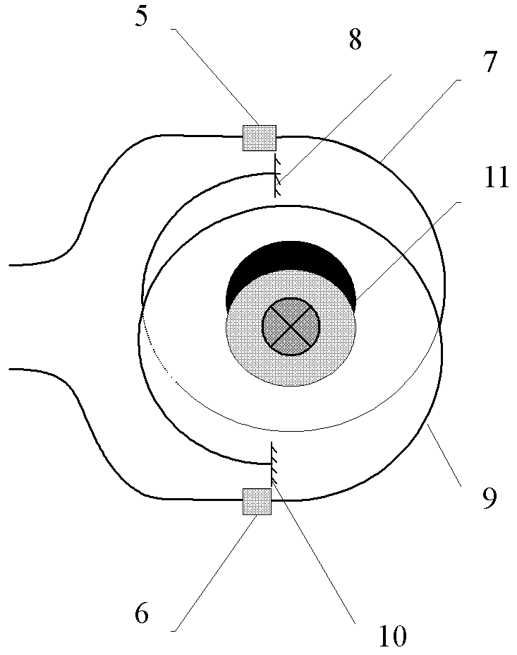
[0028] see figure 1 , the present invention provides a fiber optic current sensor coil, including a first current sensing optical path wound on the current to be measured, the fiber optic current sensor also includes a coil wound on the current to be measured and wound with the first current sensing optical path Control the second current sensing optical path in the opposite direction.

[0029] The second current sensing optical path includes a second quarter-wave plate 6, a second sensing fiber 9 and a second mirror 10; the second quarter-wave plate 6 is connected to the second sensing fiber 9 through the second Reflector 10; the second sensing fiber 9 is wound on the current 11 to be measured. The first current sensing optical path comprises a first quarter-wave plate 5, a first sensing fiber 7 and a first reflector 8; the first quarter-wave plate 5 is connected to the first Mirror 8; the first sensing fiber 7 is wound on the current 11 to be measured. The winding directi...


PUM


Abstract

The invention relates to a coil of an optical fiber current sensor and the optical fiber current sensor. The coil comprises a first current sensing light path which is wound on a current to be measured and a second current sensing light path which is wound on the current to be measured and is opposite to the first current sensing light path in winding direction. The invention provides the coil of the optical fiber current sensor and the optical fiber current sensor, which are high in sensitivity and precision, are insensitive to vibration as the Sagnac effect can be eliminated, and are insensitive to a temperature as double-light-path sensing is adopted.

Description

technical field [0001] The invention belongs to the technical field of optical fiber sensing and relates to a sensor, in particular to an optical fiber current sensor coil and an optical fiber current sensor. Background technique [0002] Current is one of the basic parameters of the power system. The measurement of current is its basic and very important task. According to the measurement results, it can provide the power system with the necessary information for metering, control and relay protection. Measurement tools have high demands. In recent years, with the rapid economic development of various countries, the demand for electric power is increasing day by day, the rated voltage level and rated current of the power system have been greatly improved, and the traditional electromagnetic current measuring equipment has become increasingly unable to meet the requirements. [0003] Optical fiber current sensing was developed to overcome the shortcomings of electromagnetic...

Claims


Application Information

Patent Timeline
Patent Type & Authority Applications(China)
IPC IPC(8): G01R15/24G01R19/00
Inventor 曹辉徐金涛赵卫石念宝王嘉刘尚波
Owner XIAN SINO HUAXIN MEASUREMENT & CONTROL
Why Eureka
Try Eureka