Fiber bragg grating current transformer with automatic temperature tracking function and automatic temperature tracking method

A technology of current transformer and optical fiber grating, which is applied in the direction of voltage/current isolation, measuring current/voltage, instruments, etc., to achieve the effect of real-time detection

Inactive Publication Date: 2012-07-04
HARBIN UNIV OF SCI & TECH
View PDF2 Cites 18 Cited by
  • Summary
  • Abstract
  • Description
  • Claims
  • Application Information

AI Technical Summary

Problems solved by technology

[0004] The purpose of the present invention is to solve the existing problem that an additional fiber grating is used to eliminate the influence of FBG drift with temperature. This solution increases the cost of the system and the complexity of the structure, and provides a temperature automatic tracking function. Fiber Bragg Grating Current Transformer and Automatic Temperature Tracking Method

Method used


Image

  • Fiber bragg grating current transformer with automatic temperature tracking function and automatic temperature tracking method
  • Fiber bragg grating current transformer with automatic temperature tracking function and automatic temperature tracking method
  • Fiber bragg grating current transformer with automatic temperature tracking function and automatic temperature tracking method

Examples


specific Embodiment approach 1

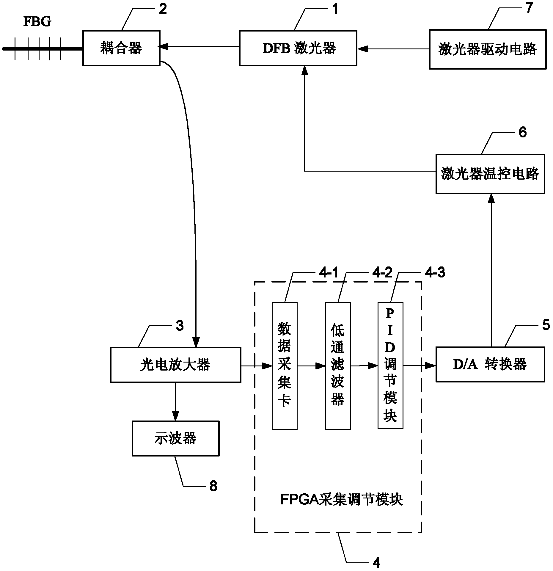
[0036] Specific implementation mode one: the following combination Figure 1 to Figure 3 Describe this embodiment mode, a kind of fiber grating current transformer with automatic temperature tracking function described in this embodiment mode, it comprises DFB laser device 1, coupler 2, photoelectric amplifier 3, FPGA acquisition adjustment module 4, D / A converter 5 and laser temperature control circuit 6,

[0037] The laser light emitted by the DFB laser 1 enters the fiber grating through the coupler 2, and the light beam reflected by the fiber grating is output to the photoelectric amplifier 3 through the coupler 2, and the photoelectric amplifier 3 converts the input optical signal into an electrical signal and outputs it to the FPGA for acquisition and adjustment. Module 4, the feedback adjustment signal output end of the FPGA acquisition and adjustment module 4 is connected to the digital signal input end of the D / A converter 5, and the analog signal output end of the D / A...

specific Embodiment approach 2

[0044] Embodiment 2: This embodiment further describes Embodiment 1. It also includes a laser driving circuit 7 for driving the DFB laser 1 to work.

specific Embodiment approach 3

[0045] Embodiment 3: This embodiment further describes Embodiment 1. It also includes an oscilloscope 8 , and the display output end of the photoelectric amplifier 3 is connected to the display input end of the oscilloscope 8 .


PUM


Abstract

The invention discloses a fiber bragg grating (FBG) current transformer with an automatic temperature tracking function and an automatic temperature tracking method, belonging to the field of photoelectricity. At present, since the technical scheme of arrangement of extra FBG is adopted for eliminating the influence of FBG drift with temperature, the system cost and the structural complexity are increased; through adoption of the FBG current transformer, the problems can be solved. The FBG current transformer comprises a distributed feedback (DFB) laser, a coupler, a photoelectric amplifier, a field programmable gate array (FPGA) acquisition and adjustment module, a digital-to-analog (D / A) converter and a laser temperature control circuit, wherein a laser beam emitted by the DFB laser enters the FBG through the coupler; a light beam reflected by the FBG is amplified by the photoelectric amplifier and converted into an electric signal which is transmitted to the FPGA acquisition and adjustment module; the FPGA acquisition and adjustment module performs proportion, integration and differentiation (PID) adjustment on the electric signal and outputs a voltage control command; and the laser temperature control circuit controls internal temperature of the DFB laser, so that the central wavelength of the DFB laser synchronously drifts with the wavelength of the FBG.

Description

technical field [0001] The invention relates to an optical fiber grating current transformer with a temperature automatic tracking function and a temperature automatic tracking method, belonging to the field of optoelectronics. Background technique [0002] Optical current transformer (OCT) is a new technology in the field of current sensing and monitoring, which is of great significance to power measurement and protection. The advantages of fiber optic current transformers, such as no explosion, no magnetic saturation, no hysteresis, small size and light weight, have been recognized and concerned by many researchers. At present, the fiber optic current transformers that are widely concerned are mainly based on the Faraday magneto-optical effect sensing scheme. This sensing scheme is affected by the linear birefringence problem and is also affected by environmental temperature factors. Fiber Bragg Grating (FBG) sensing technology is the most reliable, most practical and wav...

Claims


Application Information

Patent Timeline
Patent Type & Authority Applications(China)
IPC IPC(8): G01R15/24G01R19/32
Inventor 赵洪刘杰张伟超蒋亮
Owner HARBIN UNIV OF SCI & TECH
Why Eureka
Try Eureka