Partition and segmentation on-line positioning method for small-current grounding faults
A low-current grounding and fault zoning technology, applied in the field of detection, can solve the problems of low reliability, prolonged power outage time, complicated operation, etc., and achieve the effects of high reliability, improved accuracy and simple operation.
- Summary
- Abstract
- Description
- Claims
- Application Information
AI Technical Summary
Problems solved by technology
Method used
Image

Examples
Embodiment approach
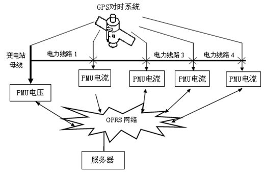
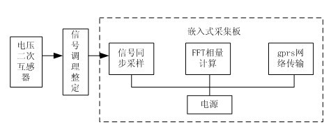
[0032] Embodiment of the present invention: Connect the secondary PT (zero-sequence voltage) terminal of the bus to the voltage measuring device at the substation side, and pay attention to the reverse connection of the secondary terminal. Select three current measurement points for the line, and connect the terminals of the zero-sequence current transformer, A, and B two-phase current transformers to the current measurement device respectively, and the secondary CT wiring cannot be reversed. The solar power supply system is designed to be installed in the middle of the pole.
[0033] After the measuring devices are powered on, they will automatically collect the phase and amplitude of zero-sequence voltage, zero-sequence current and two-phase line current, and send them back to the background monitoring server. After the server receives the data from GPRS, it will store the data. Based on these data, the location of the faulty line section is carried out.
[0034] The subst...
PUM
 Abstract
Description
Claims
Application Information