
Plane parallel three-degree-of-freedom precise operating platform

A technology of operating platform and degrees of freedom, applied in microscopes, optics, instruments, etc., can solve the problem that the displacement resolution of piezoelectric actuators and flexible hinge structures cannot be effectively used, and the high-precision motion accuracy, end motion accuracy and positioning of the operating platform cannot be achieved. Accuracy reduction and other problems, to achieve the effect of wide practicability, increase the range of motion, and reduce the installation space

Inactive Publication Date: 2012-07-04
CHINA UNIV OF MINING & TECH
View PDF3 Cites 16 Cited by
  • Summary
  • Abstract
  • Description
  • Claims
  • Application Information

AI Technical Summary

Problems solved by technology

At present, the precision operation platform built in series will produce error accumulation effect in the motion transmission process, which will reduce the motion accuracy and positioning accuracy of the end; in addition, the precision operation platform is constructed by using circular arc flexible hinges. Due to the limitation of the hinge deformation, the operation The range of movement of the platform is limited; in terms of the pose measurement of the operating platform, due to the limitation of the installation space, it is impossible to install a high-precision optical measurement system, and the kinematic equation is used to solve the pose of the end of the movement and perform open-loop control , cannot effectively utilize the high displacement resolution of the piezoelectric actuator and the flexible hinge structure, and cannot meet the high-precision movement accuracy requirements of the operating platform

Method used

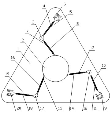
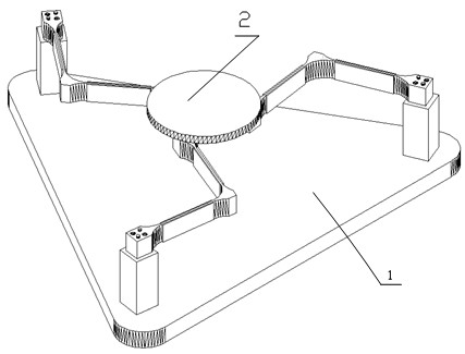
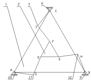

Image

  • Plane parallel three-degree-of-freedom precise operating platform
  • Plane parallel three-degree-of-freedom precise operating platform
  • Plane parallel three-degree-of-freedom precise operating platform

Examples


Embodiment Construction

[0018] The present invention will be further described below in conjunction with the embodiment in the accompanying drawings:

[0019] Such as figure 1 and figure 2 As shown, the brackets 6, 9, 20 are fixedly connected on the base 1, and the stage 2 is connected to the brackets 6, 9, 20 through three flexible transmission links 3, 12, 17. The three flexible transmission links 3 , 12 , 17 are distributed around the stage 2 in sequence.

[0020] One end of the flexible transmission link 3 is fixedly connected to the support 6, and the other end is fixedly connected to the stage 2; one end of the flexible transmission link 12 is fixedly connected to the support 9, and the other end is fixed to the stage 2 Connection; one end of the flexible transmission link 17 is fixedly connected to the bracket 20 , and the other end is fixedly connected to the stage 2 .

[0021] Such as image 3 As shown, the geometric centers C, B, A of the connecting parts of the brackets 6, 9, 20 and t...


PUM


Abstract

The invention discloses a plane parallel three-degree-of-freedom precise operating platform which comprises a base and an objective table arranged on the base; the base is fixedly connected with three supports, and the objective platform is connected with the three supports mutually through three flexible transmission connecting rods; the three flexible transmission connecting rods are distributed around the objective table, and one end of each flexible transmission connecting rod is fixedly connected to the objective table, and the other end of each flexible transmission connecting rod is fixedly connected with the support corresponding to the flexible transmission connecting rod; a resistance strain gauge and a piezoelectric bimorph are pasted on each flexible transmission connecting rod; each two connecting lines of geometric centers of the connecting parts of the supports and the flexible transmission connecting rods form a triangle; each two connecting lines of geometric centers of the connecting parts of the flexible transmission connecting rods and the objective table form another triangle; and the resistance strain gauge and the piezoelectric bimorph are connected with a closed loop feedback control system which enables the objective table to implement plane two-degree-of-freedom shifting motion and rotating motion around the geometric center of the objective table. The plane parallel three-degree-of-freedom precise operating platform provided by the invention has the advantages of simple structure, small mounting space, and high motion accuracy and positioning accuracy.

Description

technical field [0001] The invention relates to an operation platform suitable for micro-operation technology, in particular to a plane parallel three-degree-of-freedom precision operation platform. Background technique [0002] Micro-manipulation technology is one of the key technologies in precision manufacturing, precision measurement and precision transmission. It is widely used in micro-assembly, ultra-precision machining, micro-technology, semiconductor technology, bioengineering and other technologies that require micro- and nano-scale displacement and positioning. within the field. As one of the key technologies, precision operation technology occupies an extremely important position in modern cutting-edge industrial production and scientific research. With the rapid development of high and new technologies such as micro-electromechanical technology, semiconductor technology, biotechnology, and precision optoelectronic technology, there are higher requirements for p...

Claims


Application Information

Patent Timeline
Patent Type & Authority Applications(China)
IPC IPC(8): G02B21/26G05D3/12
Inventor 杨雪锋李威王禹桥樊启豪陈涤缨刘玉飞
Owner CHINA UNIV OF MINING & TECH
Learn More