Omnidirectional short-wave high-gain antenna array suitable for use over near, middle and far communication distances

A high-gain antenna and communication distance technology, applied to independent antenna unit combinations, antenna unit combinations with different polarization directions, antennas, etc., can solve the problem of not being able to provide users with multiple short-wave broadband antennas, and the antenna field occupies a large area , the number of antennas is small, etc., to save space and support rods, easy to withstand high power, and small wind resistance

Active Publication Date: 2014-03-12
SHAANXI HAITONG ANTENNA
View PDF6 Cites 0 Cited by
  • Summary
  • Abstract
  • Description
  • Claims
  • Application Information

AI Technical Summary

Problems solved by technology

[0002] Short-wave is one of the most important means for civilian and military use to achieve short-, medium-, and long-distance communications. With the rapid development of information technology, the electromagnetic environment is becoming more and more harsh. In order to resist interference and achieve reliable short-wave communication, it is necessary to increase the short-wave antenna. Gain, in addition to the use of high-gain unit short-wave antennas, but the most effective method is to use unit high-gain short-wave antenna arrays, but the existing technology is used for long-distance horizontal in-phase antenna arrays with a very small number, and most of them use The short-wave communication antennas for near, medium and long distances are multi-unit antennas, such as one-unit cage antennas, branch cage antennas, biconical monopole antennas, three-wire and four-wire short-wave broadband antennas loaded with lossy components, and sector cone antennas. And umbrella cone antennas, these antennas not only have low gain, but also occupy a large area in the antenna field of the transceiver station, and the number of antennas is small. In addition, due to the high cost of land, it is difficult to find a large site to install and erect antennas in the new antenna field
It is impossible to provide users with multiple short-wave broadband antennas in a limited space

Method used


Image

  • Omnidirectional short-wave high-gain antenna array suitable for use over near, middle and far communication distances
  • Omnidirectional short-wave high-gain antenna array suitable for use over near, middle and far communication distances
  • Omnidirectional short-wave high-gain antenna array suitable for use over near, middle and far communication distances

Examples


Embodiment 1

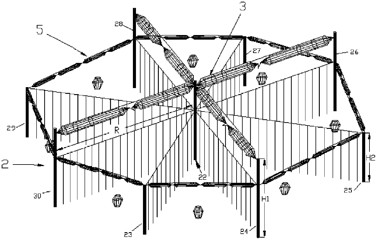
[0039] refer to figure 1 , the omnidirectional short-wave high-gain antenna array of the present invention includes a vertically polarized antenna and a horizontally polarized antenna, wherein:

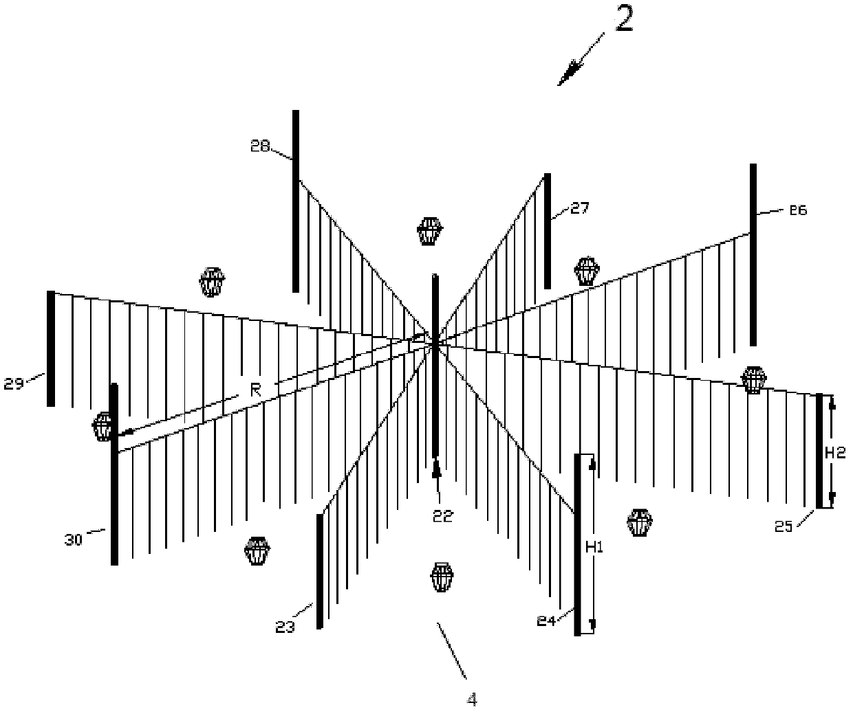
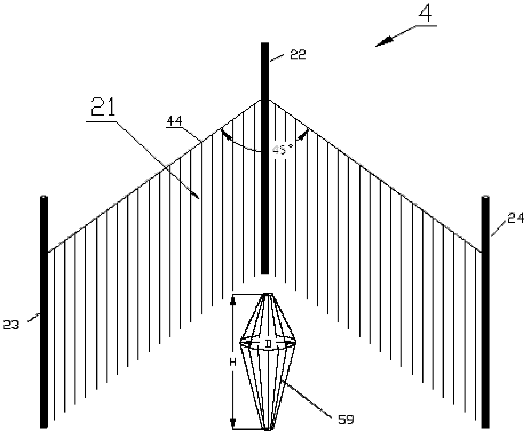
[0040] The vertically polarized antenna adopts an omnidirectional circular array antenna 2 composed of N sub-corner reflector antennas 4, 4≤N≤12. This example provides 8 sub-corner reflector antennas, but not limited to 8 pairs. The structure of the omnidirectional circular array antenna 2, such as figure 2 As shown, it is formed by connecting 8 pairs of corner reflector antennas 4 with the same structural size in the 8-30MHz frequency band. The structure of each corner reflector antenna 4 is as follows image 3 As shown, it includes a corner reflector 21, a broadband biconical monopole radiation unit 59 and a support rod. The corner reflector 21 is composed of two metal mesh surfaces with an included angle a, 90°≤a≤30°, and the metal mesh surface is composed of a plurality of ver...

Embodiment 2

[0046] refer to Figure 7 , the omnidirectional short-wave high-gain antenna array of the present invention includes a vertically polarized antenna and a horizontally polarized antenna, wherein:

[0047] The vertically polarized antenna adopts a high-frequency band omnidirectional circular array antenna 60 composed of N pairs of log-periodic antennas 61, 4≤N≤12. This example gives 8 pairs of log-periodic antennas, but is not limited to 8 pairs.

[0048] The structure of each log-periodic antenna 61 is as follows Figure 9 As shown, it consists of a plurality of vertical metal wires and feeder support rods 22. The structure of the high-frequency band omnidirectional circular array antenna 60, such as Figure 8 As shown, it is formed by connecting 8 pairs of logarithmic periodic antennas 61 with exactly the same structural size in the 8-30MHz frequency band. The structural dimensions of the 8 pairs of logarithmic periodic antennas 61 are exactly the same, and they are arrange...


PUM


Abstract

The invention provides an omnidirectional short-wave high-gain antenna array, which mainly solves the problems of the short-wave station antenna in prior arts including large occupied area, small quantity and low gain. The omnidirectional short-wave high-gain antenna array comprises vertically-polarized antennae and horizontally-polarized antennae, wherein the vertically-polarized antennae are omnidirectional circular array antennae composed of a plurality of pairs of corner reflector antennae (4) or log-periodic antennae (61) and a supporting rod; and the horizontally-polarized antennae comprise a low-frequency horizontally-polarized antenna (3) and a high-frequency horizontally-polarized antenna (5). The low-frequency horizontally-polarized antenna (3) is composed of two pairs of binary orthogonal horizontally-polarized branched cage type array antennas (7), and the high-frequency horizontally-polarized antenna (5) is composed of a plurality of pairs of binary horizontally-polarized branched cage type array antennas (51) with same structures. The low-frequency horizontally-polarized antenna (3) and the high-frequency horizontally-polarized antenna (5) are fixed on the surface and the circumference of the omnidirectional circular array antenna, respectively. The omnidirectional short-wave high-gain antenna array has the advantages of small occupied area and high antenna gain and can be used as a communication antenna of near, middle and far distances.

Description

technical field [0001] The invention relates to the technical field of antennas, in particular to a combined omnidirectional high-gain short-wave antenna array suitable for short-, medium-, and long-distance communications. Background technique [0002] Short-wave is one of the most important means for civilian and military use to achieve short-, medium-, and long-distance communications. With the rapid development of information technology, the electromagnetic environment is becoming more and more harsh. In order to resist interference and achieve reliable short-wave communication, it is necessary to increase the short-wave antenna. Gain, in addition to the use of high-gain unit short-wave antennas, but the most effective method is to use unit high-gain short-wave antenna arrays, but the existing technology is used for long-distance horizontal in-phase antenna arrays with a very small number, and most of them use The short-wave communication antennas for near, medium and lo...

Claims


Application Information

Patent Timeline
Patent Type & Authority Patents(China)
IPC IPC(8): H01Q21/24H01Q21/30H01Q19/10H01Q1/12H01Q1/52
Inventor 俱新德陶伟刘军州赵玉军张培团时长永
Owner SHAANXI HAITONG ANTENNA
Why Eureka
Try Eureka