
Novel high-efficiency inner circulation oil-cooling iron remover

A technology of internal circulation and iron remover, which is applied in the direction of high gradient magnetic separator, high gradient magnetic separation, chemical instruments and methods, etc., can solve problems such as the failure of iron remover to work normally, solder joint cracking and oil leakage, complex oil circuit layout, etc. , to achieve the effects of reducing solder joint leakage, improving performance, and oil circulation is even and reasonable

Inactive Publication Date: 2012-07-11
LONGI MAGNET CO LTD
View PDF0 Cites 9 Cited by
  • Summary
  • Abstract
  • Description
  • Claims
  • Application Information

AI Technical Summary

Problems solved by technology

At present, the commonly used circulating oil-cooled iron remover is an external circulation structure, the oil circuit layout is relatively complicated, and there are many solder joints, which are prone to solder joint cracking and oil leakage, which makes the iron remover unable to work normally and reduces the iron removal efficiency.

Method used


Image

  • Novel high-efficiency inner circulation oil-cooling iron remover
  • Novel high-efficiency inner circulation oil-cooling iron remover
  • Novel high-efficiency inner circulation oil-cooling iron remover

Examples


Embodiment Construction

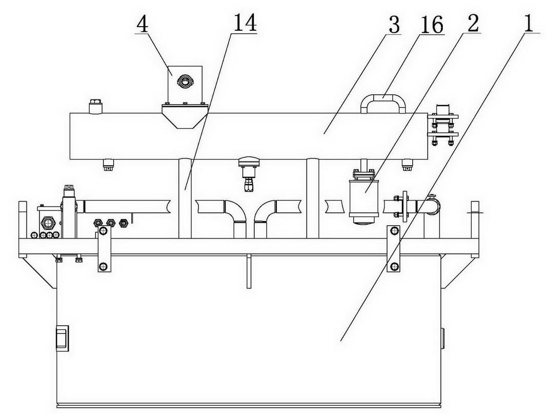
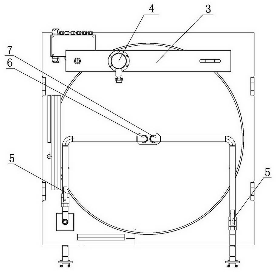
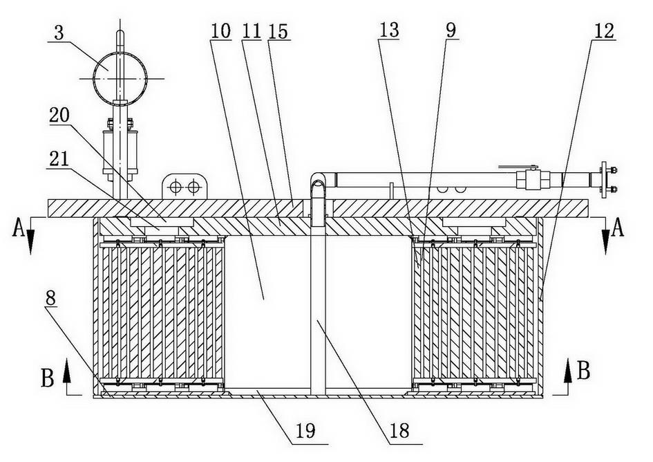
[0011] As shown in the figure, the present invention includes a sealed casing 1 composed of a yoke plate, a supporting plate 8 and a magnetically conductive plate 12 and a magnetic system inside the casing 1 . The magnetic system 1 is composed of an iron core 10 and a coil 13 wound outside the iron core 10 . The coil 13 is a multi-layer structure, and oil passages 9 are left between the layers. The yoke plate is composed of a large yoke plate 15 at the top and a small yoke plate 11 at the bottom. The large yoke plate 15 is provided with an oil inlet pipe 6 , an oil outlet pipe 7 and an oil conservator 3 . There is a valve 5 at the inlet of the oil inlet pipe 6 and the outlet of the oil outlet pipe 7. When the valve is closed during equipment maintenance, the external radiator and circulation pump can be repaired, which shortens the maintenance time and ensures the production of the iron remover. continuity. The junction box 4 of the coil 13 is arranged on the top of the oil...


PUM


Abstract

The invention discloses a novel high-efficiency inner circulation oil-cooling iron remover which comprises a shell formed by a yoke plate, a support plate and a magnetic conductive plate, and a magnetic system arranged in the shell, wherein the magnetic system comprises an iron core and a coil which is wound at the outer side of the iron core and is provided with an oil duct; an oil inlet pipe, an oil outlet pipe and an oil conservator are arranged at the upper side of the yoke plate; the iron core is internally provided with an oil injection channel; an oil return channel and an oil inlet channel are respectively arranged in the yoke plate arranged at the upper part of the iron core and at the bottom of the iron core; and the oil inlet pipe is communicated with the oil outlet pipe through the oil injection channel, the oil inlet channel and the oil return channel. After an inner circulation structure is adopted by the novel high-efficiency inner circulation oil-cooling iron remover, an external circulation pipeline is simplified, the leakage of a welding spot can be reduced, the iron remover can be guaranteed to normally work, and the iron removal efficiency can be improved. Meanwhile, due to the inner circulation structure, the oil way circulation is evener and more reasonable, the temperature rise of the iron remover is effectively reduced and guaranteed to be lower than 40 DEG C, the iron removal performance is improved, and the performance of the iron remover is far higher than the industry standard.

Description

1. Technical field [0001] The invention belongs to the technical field of iron removers, and in particular relates to a novel high-efficiency internal circulation oil-cooled iron remover. 2. Background technology [0002] Because of its small size, light weight, and low temperature rise, circulating oil-cooled iron separators have been widely used in coal, electric power, and port industries. At present, the commonly used circulating oil-cooled iron remover is an external circulation structure, the oil circuit layout is relatively complicated, and there are many solder joints, which are prone to cracking and oil leakage, which makes the iron remover unable to work normally and reduces the iron removal efficiency. 3. Contents of the invention [0003] The purpose of the present invention is to provide a new high-efficiency internal circulation oil-cooled iron remover that can effectively reduce the phenomenon of solder joint cracking and oil leakage. [0004] In order to a...

Claims


Application Information

Patent Timeline
IPC IPC(8): B03C1/02
CPCB03C1/02B03C1/031B03C1/002B03C1/025B03C1/0335B03C1/035B03C1/28B03C1/288B03C2201/18H01F27/12H01F27/14H01F27/24H01F27/28H01F27/2876H01F27/32H01F27/324H01F27/33H01F27/346
Inventor 张承臣张成武李红旭赵迎刘福郭美生毕世宽
Owner LONGI MAGNET CO LTD
Learn More