TIG (tungsten inert gas) welding method for auxiliary mechanical vibration droplet transfer and TIG welding device for same

A technology of mechanical vibration and droplet transfer, applied in welding equipment, welding accessories, arc welding equipment, etc., can solve the problems of uneven structure of welding seam, affecting the stability of arc, large width of heat-affected zone, etc., and achieve uniform structure. The effect of good performance, improved efficiency, and accelerated droplet transfer frequency

Active Publication Date: 2012-07-11
SHENYANG JINCHANG LANYU NEW MATERIAL CO LTD
View PDF5 Cites 20 Cited by
  • Summary
  • Abstract
  • Description
  • Claims
  • Application Information

AI Technical Summary

Problems solved by technology

For conventional automatic wire-feeding TIG welding, the welding wire is heated and melted by the arc, and the droplet mainly relies on its own gravity and arc force to break away from the shackles of the surface tension at the end of the welding wire to achieve the transition. There are the following disadvantages: (1) The droplet is larger than The droplet transitions to the molten pool, which has a large impact on the molten pool and is prone to splashing; (2) The molten droplet absorbs more arc energy, and the molten droplet is overheated, which is likely to cause inhomogeneity of the weld structure, and the width of the heat-affected zone is large; (3) Large droplet transfer leads to slow droplet transfer and low deposition efficiency
The high cost of CMT and STT melting gas shielded welding technology is the key factor limiting its popularization and application. At the same time, the drastic change of current during welding will inevitably affect the stability of the arc.

Method used


Image

  • TIG (tungsten inert gas) welding method for auxiliary mechanical vibration droplet transfer and TIG welding device for same
  • TIG (tungsten inert gas) welding method for auxiliary mechanical vibration droplet transfer and TIG welding device for same
  • TIG (tungsten inert gas) welding method for auxiliary mechanical vibration droplet transfer and TIG welding device for same

Examples


Embodiment 1

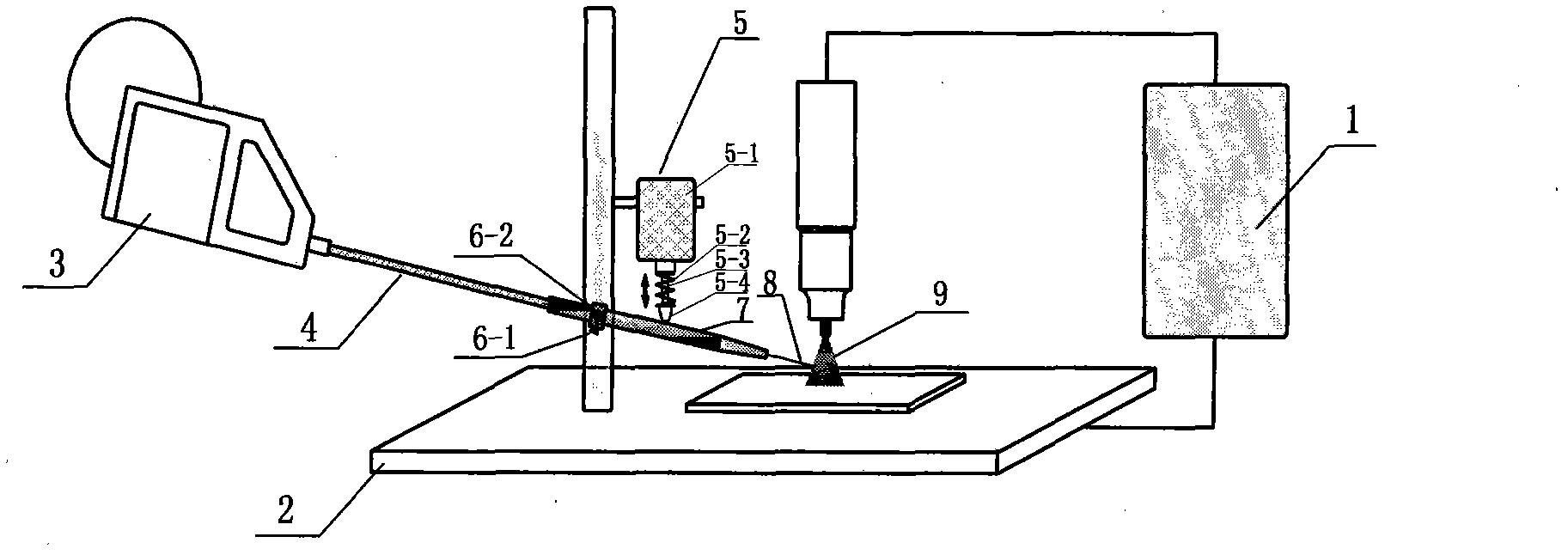
[0022] Example 1: Combining figure 1 , the present invention a kind of TIG welding device of mechanical vibration auxiliary droplet transfer, it is by TIG power supply (1), frame (2), wire feeder (3), conduit (4), auxiliary mechanical vibration device (5) , wire feeder (7) and welding wire (8), the wire feeder (3) is connected to the conduit (4), the conduit (4) is connected to the wire feeder (7), and the wire feeder (7) is connected to the frame (2 ) are firmly connected, and the auxiliary mechanical vibration device (5) is fixed on the frame (2).

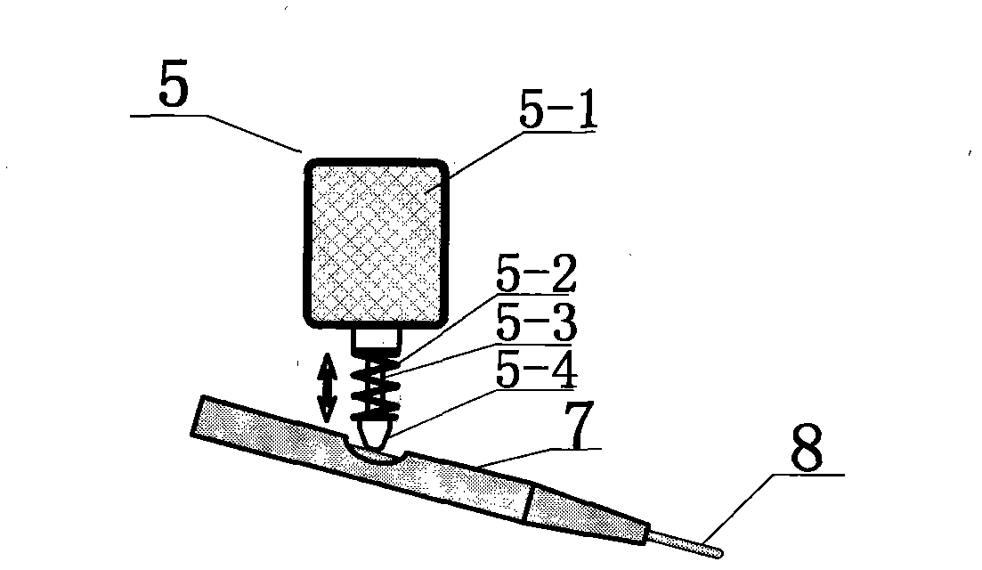
[0023] Described auxiliary mechanical vibrating device (5) comprises fuselage (5-1), buffer spring (5-2), vibrating bar (5-3) and contact (5-4), is built-in by fuselage drive motor and The transmission device drives the vibrating rod (5-3) to reciprocate up and down, the vibrating rod (5-3) and the contact (5-4) are threaded, and the vibrating rod (5-3) and the contact (5-4) A buffer spring (5-2) is sleeved between, and the buf...

Embodiment 2

[0029] Example 2: Combining figure 1 , figure 2 , the present invention is a mechanical vibration-assisted droplet transfer TIG welding method, the welding wire material is a material with high hardness and good rigidity, such as stainless steel. The welding wire (8) is output by the wire feeder (3), enters the arc (9) area after passing through the conduit (4) and the wire feed nozzle (7), and processes a process groove of an appropriate size on the wire feed nozzle (7). Both the vibrating effect and the stability of the wire feed nozzle (7) need to be combined, and the size of the slot is determined by the front end of the contact (5-4), so as to fully transmit the vibration effect.

[0030]The principle of realizing the cold metal transition is that the auxiliary mechanical vibration device (5) causes the vibration rod (5-3) to generate mechanical vibration, and the contact (5-4) and the vibration rod (5-3) reciprocate up and down, and the vibration is caused by the conta...

Embodiment 3

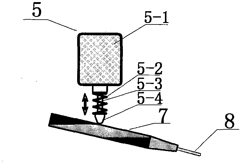
[0031] Embodiment 3: The welding wire is a material with low hardness and poor rigidity, such as tin. At this time, the contact (5-4) is in direct contact with the outer wall of the wire feeding nozzle (7), avoiding the deformation of the welding wire (8) caused by mechanical vibration, and destroying the continuity of the automatic wire feeding process. The vibration is transmitted from the contact (5-4) to the The wire feed nozzle (7) is then transmitted to the welding wire (8), and an additional mechanical force is generated at the end of the welding wire (8). Other steps, connection methods and principles are the same as those in Embodiment 2.

[0032] By adjusting the rotational speed of the built-in driving motor of the auxiliary mechanical vibration device (5), the mechanical vibration of the vibration rod (5-3) within the frequency range of 2 to 30 times per second can be realized, and a higher vibration frequency can be selected for welding wires with larger diameters ...


PUM


Abstract

The invention provides a TIG (tungsten inert gas) welding method for auxiliary mechanical vibration droplet transfer and a TIG welding device for the same. The TIG welding device comprises a TIG power supply, a wire feeder, a guide tube, an auxiliary mechanical vibration device, a wire feeding nozzle and a welding wire, wherein the wire feeder is connected with the guide tube, the guide tube is connected with the wire feeding nozzle, and the auxiliary mechanical vibration device is fixed to a frame. A vibration rod is driven to vertically vibrate in a reciprocating manner by an internal body driving motor and a transmission device, and a buffer spring is sleeved between the vibration rod and a contact. The TIG welding method includes the steps: igniting an arc heating workpiece, forming a molten bath after arc is stable, and then starting the wire feeder to automatically feed in the welding wire; and starting the auxiliary mechanical vibration device, leading the vibration rod, the contact and the welding wire to mechanically vibrate, and performing welding under the action of auxiliary mechanical vibration. The TIG welding device is simple, convenient in operation and high in applicability, and compared with digital control equipment, the TIG welding device greatly reduces cost and is convenient for industrial popularization.

Description

(1) Technical field [0001] The invention relates to a welding technology, in particular to a TIG welding method and a device thereof in which mechanical vibration assists droplet transfer. (2) Background technology [0002] Tungsten argon arc welding (TIG) has the characteristics of high welding quality, stable arc, and wide application range. It is a welding method commonly used in actual production. According to different wire feeding methods, tungsten argon arc welding (TIG) can be divided into manual wire feeding and automatic wire feeding. For conventional automatic wire-feeding TIG welding, the welding wire is heated and melted by the arc, and the droplet mainly relies on its own gravity and arc force to break away from the shackles of the surface tension at the end of the welding wire to achieve the transition. There are the following disadvantages: (1) The droplet is larger than The droplet transitions to the molten pool, which has a large impact on the molten pool ...

Claims


Application Information

Patent Timeline
Patent Type & Authority Applications(China)
IPC IPC(8): B23K9/167B23K9/32
Inventor 吕世雄黄永宪徐永强敬小军郑传奇张若蘅张有为
Owner SHENYANG JINCHANG LANYU NEW MATERIAL CO LTD
Why Eureka
Try Eureka