Tail gas collecting system of silicon carbide smelting furnace

A technology for exhaust gas collection and smelting furnace, applied in silicon carbide, carbide and other directions, can solve the problems of inability to collect gas, environmental pollution, waste, etc., to reduce CO pollution to the environment and harm to workers' health and investment costs Low cost and the effect of reducing security risks

Inactive Publication Date: 2012-07-11
XIAN UNIV OF SCI & TECH
View PDF3 Cites 6 Cited by
  • Summary
  • Abstract
  • Description
  • Claims
  • Application Information

AI Technical Summary

Problems solved by technology

[0002] At present, in the production of silicon carbide, a large amount of smelting tail gas mainly composed of CO is produced. CO can be used as fuel or basic chemical raw material, which has excellent economic value, but the existing technology cannot collect the gas generated in the smelting of silicon carbide , almost all silicon carbide manufacturers in China directly burn CO gas
The disadvantage of this method is that: on the one hand, CO combustion produces a large amount of CO 2 Greenhouse gas, leading to environmental pollution; on the other hand, the added value of CO is not fully utilized, resulting in great waste
The disadvantages of this method are as follows: First, the risk of CO gas accumulation and explosion is increased. In the production of silicon carbide, the temperature is high, the time is long, the furnace is easy to spray, and the gas purity fluctuates greatly in stages, etc., which are all in line with the conditions of CO gas explosion. The second is that there is no effective control of the power system for extracting CO from the outside. During the production of silicon carbide, the interior of the material reaction system is under positive pressure due to the generation of a large amount of CO gas. If the power system for extracting CO is not effectively controlled, once CO is extracted The rate is greater than the generation rate of CO gas inside the material reaction system, and the normal reaction conditions of silicon carbide will be destroyed, which is not conducive to the production of silicon carbide

Method used


Image

  • Tail gas collecting system of silicon carbide smelting furnace
  • Tail gas collecting system of silicon carbide smelting furnace
  • Tail gas collecting system of silicon carbide smelting furnace

Examples


Embodiment Construction

[0029] The invention will be further described below by means of the accompanying drawings and specific embodiments.

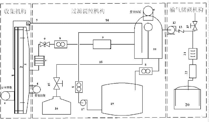
[0030] Such as figure 1 As shown, the silicon carbide smelting furnace exhaust gas collection system includes three interconnected collection mechanisms, filtration and purification mechanisms, and gas transmission and storage mechanisms. Among them: the collection mechanism is connected with the smelting furnace wall of the system, and the collection mechanism is in turn connected with the filtration and purification mechanism It is connected with the gas transmission and storage mechanism; the collection mechanism and the filtration and purification mechanism are respectively equipped with safety control mechanisms.

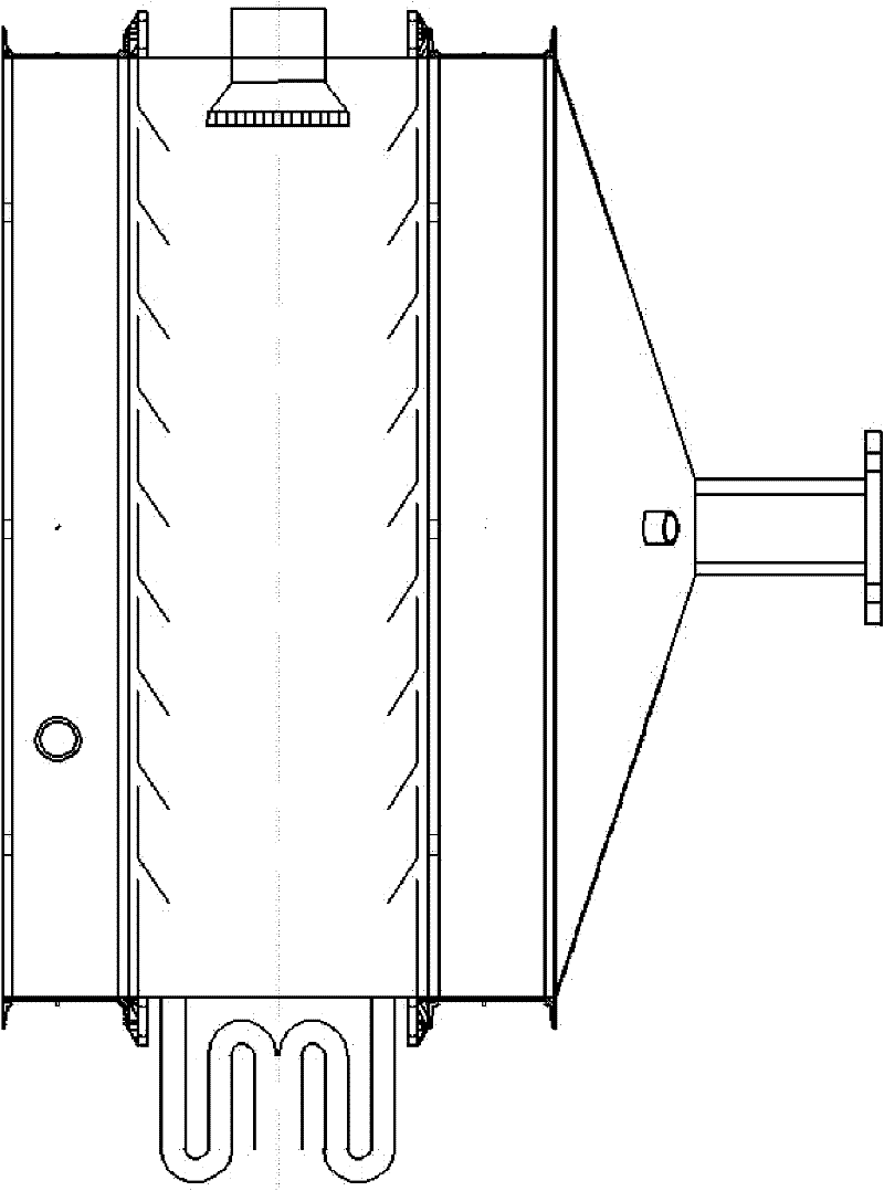
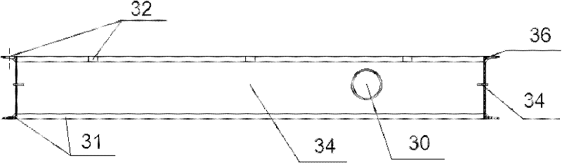
[0031] The collection mechanism includes a collection cover base 1, a collection cover 3 and shutters 2. The collection cover base 1 is fixedly connected to the furnace wall of the smelting furnace, and the collection cover 3 is connected to on...


PUM


Abstract

The invention discloses a tail gas collecting system of a silicon carbide smelting furnace, which comprises a collecting mechanism, a filtering and purifying system and a gas transmission storage mechanism which are mutually connected, wherein the collecting mechanism is connected with a furnace wall of the smelting furnace of the system, and is then sequentially connected with the filtering and purifying mechanism and the gas transmission storage mechanism; the collecting mechanism and the filtering and purifying mechanism are respectively provided with a safety control mechanism; the collecting mechanism comprises a collecting cover base, a collecting cover and a shutter; the filtering and purifying mechanism comprises a gas separator, an oil storage tank and a water tank which are connected respectively through a pipeline; the gas separator is connected with the gas transmission storage mechanism through a pipeline; the gas transmission storage mechanism comprises a gas storage tank connected with the gas separator. The system can fully utilize the additional value of tail gases such as CO generated in the silicon carbide smelting process, and the environment pollution is reduced; and the danger of CO gas gathering and explosion is reduced, and the normal reaction conditions of silicon carbide can not be damaged.

Description

technical field [0001] The invention belongs to the field of silicon carbide smelting and tail gas treatment, and in particular relates to a silicon carbide smelting furnace tail gas collection system. Background technique [0002] At present, in the production of silicon carbide, a large amount of smelting tail gas mainly composed of CO is produced. CO can be used as fuel or basic chemical raw material, which has excellent economic value, but the existing technology cannot collect the gas generated in the smelting of silicon carbide , almost all domestic silicon carbide manufacturers directly burn CO gas. The disadvantage of this method is that: on the one hand, CO combustion produces a large amount of CO 2 Greenhouse gas, leading to environmental pollution; on the other hand, the added value of CO is not fully utilized, resulting in great waste. For this reason, relevant experts at home and abroad have studied the exhaust gas collection of silicon smelting furnaces and m...

Claims


Application Information

Patent Timeline
Patent Type & Authority Applications(China)
IPC IPC(8): C01B31/36C01B32/956
Inventor 邵水源彭龙贵宋昌清王刚庞青涛
Owner XIAN UNIV OF SCI & TECH
Why Eureka
Try Eureka