
Chemical-mechanical polishing liquid

A chemical mechanical and polishing liquid technology, applied in the direction of polishing compositions containing abrasives, etc., to achieve good stability and small scratches

Active Publication Date: 2012-07-11
ANJI MICROELECTRONICS (SHANGHAI) CO LTD
View PDF3 Cites 7 Cited by
  • Summary
  • Abstract
  • Description
  • Claims
  • Application Information

AI Technical Summary

Problems solved by technology

[0005] The purpose of the invention is to solve the problem of the polishing selectivity ratio of high-density silicon dioxide (HDP-Oxide) and silicon nitride in the shallow trench isolation polishing process
Improve planarization efficiency

Method used


Image

  • Chemical-mechanical polishing liquid
  • Chemical-mechanical polishing liquid

Examples


Embodiment Construction

[0009] The present invention is further illustrated by the method of embodiment below, does not therefore limit the present invention among the scope of described embodiment.

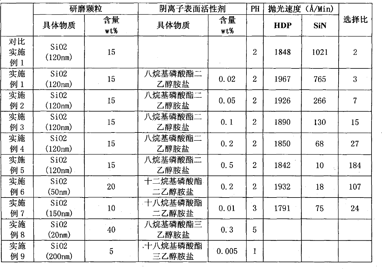
[0010] Table 1 has provided the chemical mechanical polishing liquid embodiment 1~9 of the present invention and the formula of comparative example, according to the formula in the table, each composition is mixed simply and evenly, and the balance is water, and then adopts potassium hydroxide, ammoniacal liquor and nitric acid After adjusting to a suitable pH value, the polishing liquid of each embodiment can be prepared.

[0011] Table 1 chemical mechanical polishing liquid embodiment 1~9 and comparative example of the present invention

[0012]

[0013] Adopt comparative example 1 and the polishing liquid of embodiment 1~7 of the present invention according to following condition to blank HDP-Oxide wafer and blank Si 3 N 4 The wafer is polished. Polishing conditions: the polishing pad is PPG 14...


PUM


Abstract

The invention discloses polishing liquid used for a shallow trench isolation polishing process. The polishing liquid contains silicon-based abrasive, anion type surfactant and water. The polishing liquid has higher removing rate of high-density silicon dioxide (HDP-Oxide) and higher selection ratio to the removing rate of silicon nitride. A polished crystal circle has perfect surface appearance and lower surface pollutant residue.

Description

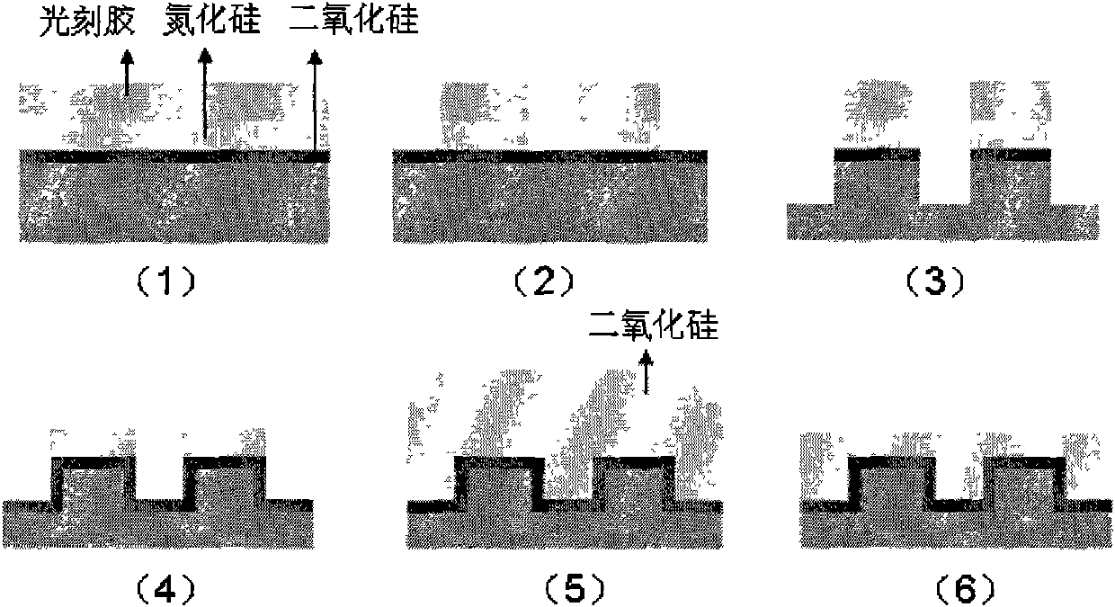
technical field [0001] The invention relates to a chemical mechanical polishing liquid. Background technique [0002] The manufacture of CMOS chips usually integrates hundreds of millions of active devices (including NMOS and PMOS) on silicon substrate materials, and then designs various circuits to realize complex logic functions and analog functions. To ensure electrical isolation between different devices, it is necessary to use insulating materials to isolate them. Shallow trench isolation (STI) is an industrialized method to form isolation regions between active devices. This isolation method is to grow a layer of silicon dioxide on the substrate, and then deposit a layer of silicon nitride film, the typical thickness of the two is 10-20nm and 50-100nm, and then apply glue, expose and develop, as in figure 1 shown. [0003] It can be seen from the figure that the steps (5)-(6) need to use CMP planarization process, which requires rapid removal of silicon dioxide and ...

Claims


Application Information

Patent Timeline
IPC IPC(8): C09G1/02
Inventor 姚颖宋伟红孙展龙
Owner ANJI MICROELECTRONICS (SHANGHAI) CO LTD
Learn More