Permanent-magnet-biased axial magnetic bearing

A technology of axial magnetic bearing and permanent magnet bias, which is applied in the direction of shaft and bearing, bearing, shaft, etc., can solve the problems of increased installation difficulty, long axial length, low critical speed, etc., and achieves convenient control, axial The effect of short length and high critical speed

Inactive Publication Date: 2012-07-11
NANJING COLLEGE OF CHEM TECH
View PDF5 Cites 14 Cited by
  • Summary
  • Abstract
  • Description
  • Claims
  • Application Information

AI Technical Summary

Problems solved by technology

[0004] At present, there are three structural forms of permanent magnet bias axial magnetic bearings researched internationally. One is to place permanent magnets in the rotor, which increases the difficulty of installation and limits its high-speed operation; the second type of magnetic bearing suspends the rotor. Placed on both sides of the stator, the axial length is long and the critical speed is low; in the third type of magnetic bearing, the axial control magnetic flux passes through the permanent magnet, which has an obvious demagnetization effect on the permanent magnet, and the magnetic flux leakage is large. Efficient applications are limited

Method used


Image

  • Permanent-magnet-biased axial magnetic bearing
  • Permanent-magnet-biased axial magnetic bearing
  • Permanent-magnet-biased axial magnetic bearing

Examples


Embodiment Construction

[0013] The embodiments of the present invention are described in detail below. This embodiment is implemented on the premise of the technical solution of the present invention, and detailed implementation methods and specific operating procedures are provided, but the protection scope of the present invention is not limited to the following implementation example.

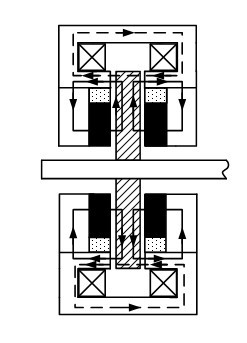
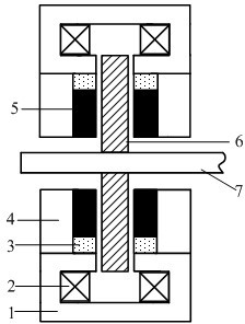
[0014] Such as figure 1 As shown, this embodiment includes a stator assembly and a rotor assembly, wherein: the stator assembly is arranged on the outer periphery of the rotor assembly. The stator assembly includes an axial stator 1, an axial control winding 2, a magnet spacer 3, a magnetic conductor 4 and a permanent magnet 5, the rotor assembly includes a rotor core 6 and a rotating shaft 7, and the axial control winding 2 is wound on the magnetic pole of the axial stator 1 , the rotor core 6 is set on the rotating shaft 7, the magnet spacer 3 is arranged in the axial stator 1 and the magnetizer 4, the outer end...


PUM


Abstract

The invention discloses a permanent-magnet-biased axial magnetic bearing in the technical field of magnetic bearings. The permanent-magnet-biased axial magnetic bearing comprises a stator assembly and a rotor assembly; the stator assembly comprises an axial stator, an axial control winding, a septum magnet, a magnetizer and a permanent magnet; the rotor assembly comprises a rotation shaft and a rotor core; the axial control winding is wound on a magnetic pole of the axial stator; the rotor core is sleeved on the rotation shaft; the magnetizer is arranged in the axial stator, and the external end of the magnetizer is connected with the internal end of the axial stator; the septum magnet is arranged in the axial stator, the external end of the septum magnet is connected with the internal end of the axial stator; the permanent magnet is adhered to one side of the magnetizer, and the external end of the permanent magnet is contacted with the inner end face of the septum magnet; and the rotor core is arranged in the axial stator. The permanent-magnet-biased axial magnetic bearing has a simple structure, and is high in critical rotation speed, and low in power consumption; and magnetic flux flows in an axial direction and is decoupled with the radial suspension force completely, so the permanent-magnet-biased axial magnetic bearing is convenient to control.

Description

technical field [0001] The invention relates to a hybrid magnetic bearing in the technical field of magnetic bearings, in particular to a permanent magnetic bias axial magnetic bearing. Background technique [0002] Magnetic suspension bearing, also referred to as magnetic bearing for short, is a new type of high-performance bearing that uses the magnetic force between the stator and the rotor to suspend the rotor in space, so that there is no mechanical contact between the stator and the rotor. Because there is no mechanical contact between the stator and the rotor, the rotor of the magnetic suspension bearing can reach a high operating speed, and has the advantages of small mechanical wear, low energy consumption, long life, no lubrication, no pollution, etc., especially suitable for high speed , vacuum and ultra-clean and other special applications. [0003] At present, magnetic bearings are divided into the following types according to the way the magnetic force is prov...

Claims


Application Information

Patent Timeline
Patent Type & Authority Applications(China)
IPC IPC(8): F16C32/04
CPCF16C2360/45
Inventor 蒋汝根赵旭升
Owner NANJING COLLEGE OF CHEM TECH
Why Eureka
Try Eureka