
Scintillation crystal array and scintillation detector possessing the same

A scintillation crystal array and scintillation detector technology, applied in the field of radiation detection, can solve problems affecting the detection efficiency of the scintillation crystal array, large gaps in the scintillation crystal array, and complicated reflective film pasting process, etc., to achieve easy implementation and mass production, and blind spots The effect of small area and easy mass production

Active Publication Date: 2012-07-11
TSINGHUA UNIV
View PDF6 Cites 27 Cited by
  • Summary
  • Abstract
  • Description
  • Claims
  • Application Information

AI Technical Summary

Problems solved by technology

[0005] However, the disadvantage of applying reflective paint is that the light reflectivity is not good enough, and the light loss is large after multiple reflections; and the paint layer has a large thickness, so the gaps in the entire scintillation crystal array are large, especially in the size of the crystal unit. When it is small, the proportion of space occupied by the paint layer is large, and the space occupied by the paint layer is the detection dead zone, which affects the detection efficiency of the scintillation crystal array
The disadvantage of pasting the reflective film is that the reflective film has a certain thickness, usually greater than 0.5 mm, and the pasting process of the reflective film is complex, time-consuming, and poor in consistency, which is not suitable for mass production

Method used


Image

  • Scintillation crystal array and scintillation detector possessing the same
  • Scintillation crystal array and scintillation detector possessing the same
  • Scintillation crystal array and scintillation detector possessing the same

Examples


Embodiment Construction

[0033] The embodiments of the present invention are described in detail below. Examples of the embodiments are shown in the accompanying drawings, in which the same or similar reference numerals indicate the same or similar elements or elements with the same or similar functions. The embodiments described below with reference to the drawings are exemplary, and are only used to explain the present invention, but should not be understood as limiting the present invention.

[0034] In the description of the present invention, it should be understood that the terms "center", "longitudinal", "transverse", "length", "width", "thickness", "upper", "lower", "front", " The orientation or positional relationship indicated by “back”, “left”, “right”, “vertical”, “horizontal”, “top”, “bottom”, “inner”, and “outer” are based on the orientation shown in the drawings or The positional relationship is only for the convenience of describing the present invention and simplifying the description, r...


PUM


Abstract

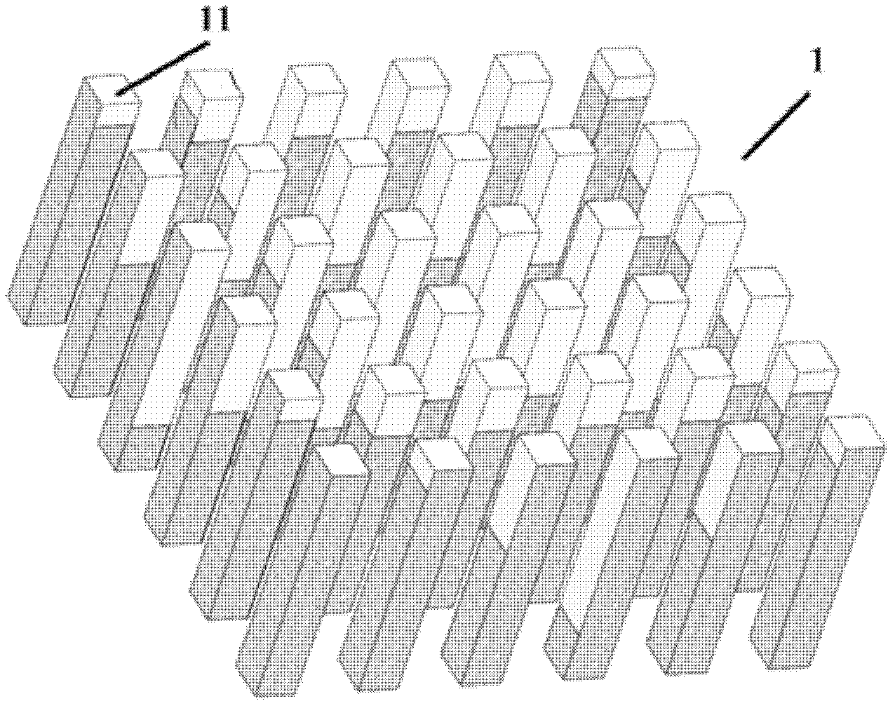
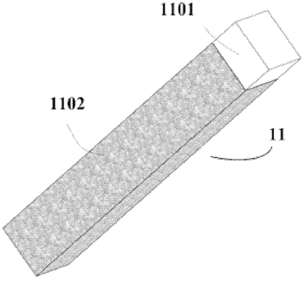
The invention provides a scintillation crystal array and a scintillation detector possessing the same. The scintillation crystal array of the invention is formed through arranging a plurality of crystal units according to a predetermined design. And the crystal units are connected with each other through an optical cement or silicone oil. One part of an external surface of the each crystal unit is coated with a reflective film so that the reflective films on a plurality of crystal units can define a light emission surface of the scintillation crystal array together. The scintillation detectorof the invention has the following advantages that flexibility is high; reflectivity is high; the structure is compact; mass production is easy.

Description

Technical field [0001] The invention belongs to the field of radiation detection technology, and particularly relates to a scintillation crystal array and a scintillation detector with the scintillation crystal array. Background technique [0002] The scintillation detector is one of the commonly used detectors for high-energy ray detection. Scintillation detectors usually use scintillation crystals that can effectively block and absorb electromagnetic wave radiation and produce luminescence with electromagnetic wave radiation as detection materials. When high-energy rays are incident into the scintillation crystal, according to the difference of ray energy, effective atomic coefficient and density of the crystal, different ratios of photoelectric effect, Compton scattering effect and electron pair effect will occur with the crystal, and the energy will be deposited in the scintillation crystal. The excited scintillation crystal de-excites scintillation light. A photodetector s...

Claims


Application Information

Patent Timeline
IPC IPC(8): G01T1/202
Inventor 刘亚强王石魏清阳马天予夏彦
Owner TSINGHUA UNIV
Learn More