Liquid film dynamic compensating device

A dynamic compensation and liquid film technology, applied in microscopes, optics, instruments, etc., can solve problems such as changing liquid properties, affecting observation quality, and deteriorating liquid quality, so as to reduce requirements, improve observation quality, and inhibit accumulation and retention Effect

Inactive Publication Date: 2014-05-07
FUZHOU UNIV
View PDF9 Cites 0 Cited by
  • Summary
  • Abstract
  • Description
  • Claims
  • Application Information

AI Technical Summary

Problems solved by technology

However, due to the non-renewal during the observation process, the liquid is easily polluted, and thus there are some problems as follows:
However, since the liquid does not flow, the pollution on the surface of the substrate and the periphery of the flow field will continue to spread and accumulate in the observation area as the observation progresses, and the quality of the liquid will deteriorate; especially for long-term observation conditions, it may even cause bacteria
This will change the properties of the liquid and cause imaging distortion for micro-nano observations
[0007] 2) With the accumulation of pollution inside the flow field, the continuous deposition of pollutants on the surface of the objective lens will seriously affect the quality of observation
However, since the liquid is in a non-flowing zero-pressure state, a certain pressure of gas applied to the edge of the liquid with a small volume will force the liquid boundary to fluctuate and increase the possibility of leakage; The way of ventilation will accelerate the evaporation of liquid and promote the generation of water spot defects

Method used


Image

  • Liquid film dynamic compensating device
  • Liquid film dynamic compensating device
  • Liquid film dynamic compensating device

Examples


Embodiment Construction

[0030] The specific implementation of the present invention will be described below in conjunction with the drawings and examples.

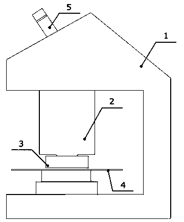
[0031] figure 1 Schematically shows the assembly of the liquid film dynamic compensation device and the lens group of the embodiment of the present invention, the liquid film dynamic compensation device 3 arranged between the lens group 2 and the substrate 4 can be used in microscopic equipment such as an immersion microscope 1 application. In actual observation, the light on the surface of the substrate 4 (silicon wafer or liquid crystal substrate, etc.) is captured by related equipment for microscopic analysis through the slit liquid film above the substrate 4 and the lens group 2 . For the consideration of equipment utilization and economy, immersion microscopic observation can have two modes: direct visual inspection and image analysis. If the wavelength of the observation light is visible light, it can be directly observed through the eyep...


PUM


Abstract

The invention discloses a liquid film dynamic compensation device. The liquid film dynamic compensation device is arranged between an optical lens and a substrate, a self-adaptive gas sealing belt is arranged at the periphery of a liquid injecting cavity, an isolation belt, a gas releasing cavity and a recovery end sealing belt are arranged at the periphery of a row of recovery holes, and thus the long-term stability of a flow field boundary under the dynamic update of the liquid is facilitated. Based on the pressure distribution characteristic of the flow field, non-uniform energy is applied to the boundary so that the liquid is facilitated to gather towards the center, and thus the impact at a low-pressure position of the flow field, caused by overlarge sealing energy, and the leakage at a high-pressure position of the flow field, caused by the shortage of the sealing energy, are avoided; and due to a corresponding structure at the periphery of the recovery holes, the sealing is reliable, the recovery gas-liquid two-phase flow is simultaneously restrained, and the stability of a system is enhanced. According to the liquid film dynamic compensation device disclosed by the invention, the flow updating of the liquid can be realized, thus the improvement of the cleanliness of the liquid at an observation area is facilitated, the reliability of observation imaging is enhanced, and the requirement for the cleanliness of the environment is lowered.

Description

technical field [0001] The invention relates to a liquid film dynamic compensation device, in particular to a liquid film dynamic compensation device used in an immersion microscope (Immersion Microscope). Background technique [0002] In industries such as semiconductors, fault analysis and reliability evaluation of tiny electronic devices are the key to ensuring yield. The usual way is to use the electronic device as a sample and observe it under a microscope to determine whether there are defects or impurities that affect the normal operation of the device. However, as the characteristic line width of electronic devices continues to shrink below 32 nanometers, and the size of substrates (such as semiconductor silicon wafers) continues to increase, the technical cost of traditional observation methods is rising rapidly. [0003] The immersion microscope system fills the thin layer gap between the front end of the objective lens and the substrate (such as silicon wafer or ...

Claims


Application Information

Patent Timeline
Patent Type & Authority Patents(China)
IPC IPC(8): G02B21/33
Inventor 陈晖杜恒陈淑梅陈传铭
Owner FUZHOU UNIV
Why Eureka
Try Eureka