Constant-speed constant-frequency wind turbine low-voltage riding-through device and control method

A low-voltage ride-through technology and wind turbine technology, applied in wind power generation, control systems, control generators, etc., can solve the cost of low-voltage ride-through devices, control complexity, difficulty in implementing engineering transformation, increase device cost and floor area, Increased difficulty of DC voltage regulation control and other issues, achieving both economical and practical, enhanced power supply reliability, and low cost effects

Inactive Publication Date: 2012-07-11
CHINA EPRI SCIENCE & TECHNOLOGY CO LTD +2
View PDF3 Cites 8 Cited by
  • Summary
  • Abstract
  • Description
  • Claims
  • Application Information

AI Technical Summary

Problems solved by technology

First, the power electronic devices in the normal working state must always work under the rated output current of the wind turbine, so the requirements for the IGBT devices are very high, and the cost will suddenly increase, and this shortcoming cannot be overcome by this series DVR solution; Second, it is not difficult to find out only from the number of applicable power electronic devices that this kind of DVR control scheme uses more full-control devices IGBT, which will inevitably lead to the complexity of the control system and the increase of device costs; third, this This control method requires the converter to establish a stable DC voltage, and the establishment of the DC voltage of the converter requires an independent DC charging circuit or relying on the active power generated by the wind turbine when the grid system fails, the former will greatly increase this. The cost and floor area of ​​the set of equipment, the latter will make the control complicated, and both of them need to suppress the overvoltage through the discharge circuit when the wind turbine feeds active power to the DVR device, and maintain the stability of the DC voltage. The difficulty of pressure control has increased
The above points all show that the low-voltage ride-through device based on the DVR principle has many deficiencies and deficiencies in terms of device cost, control complexity, and difficulty in implementing engineering transformation.

Method used


Image

  • Constant-speed constant-frequency wind turbine low-voltage riding-through device and control method
  • Constant-speed constant-frequency wind turbine low-voltage riding-through device and control method
  • Constant-speed constant-frequency wind turbine low-voltage riding-through device and control method

Examples


Embodiment 1

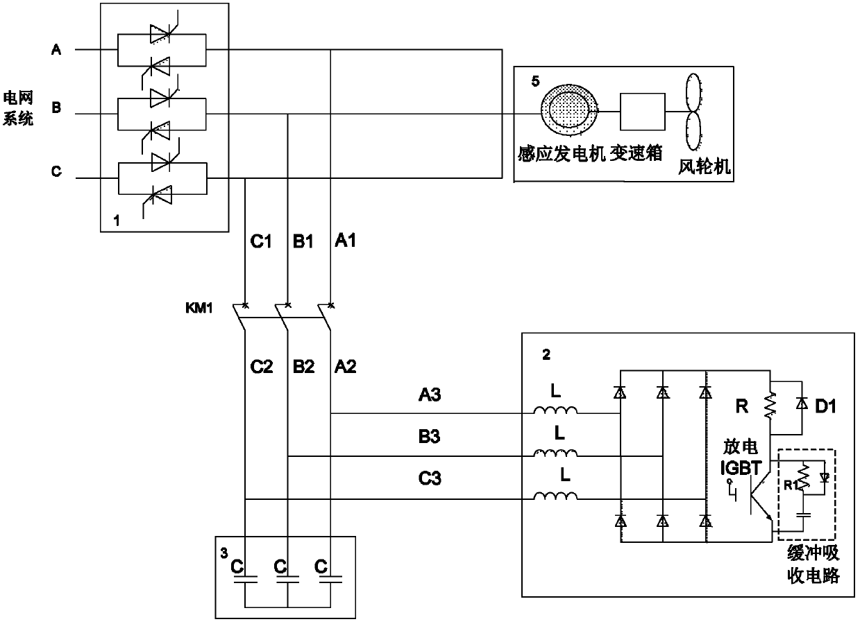
[0039] Such as figure 2As shown, the low voltage ride-through device of this embodiment connects a switch in series between the grid system and the wind turbine; connects a series contactor and a reactive power compensation module in parallel between the switch and the wind turbine; The active power absorption circuit is connected in parallel between the contactor and the reactive power compensation module; the switch is an electronic switch or a mechanical switch, and the electronic switch includes an anti-parallel thyristor or an anti-parallel GTO. This embodiment takes the anti-parallel thyristor valve of electronic switch as an example, which is used to cut off the channel for the wind turbine to feed active power to the grid system when a voltage sag occurs in the grid system, and quickly connect the wind turbine to the grid system after the grid system voltage recovers. Grid system connectivity. The reactive power compensation module is a parallel capacitor bank, which...

Embodiment 2

[0052] This embodiment is basically the same as Embodiment 1, the difference is:

[0053] The active absorption circuit of this embodiment has another form, such as image 3 shown. That is, it includes a reactor, a three-phase uncontrollable rectifier bridge, a discharge resistor, a discharge IGBT and an IGBT snubber snubber circuit; three reactors, each of which is connected in series with the discharge resistor and the three-phase uncontrollable rectifier bridge in sequence, so The three-phase uncontrollable rectifier bridge is connected in parallel with the discharging IGBT, and the discharging IGBT is connected in parallel with the IGBT snubbing circuit.

[0054] The control method of the device is the same as that in the first embodiment.

Embodiment 3

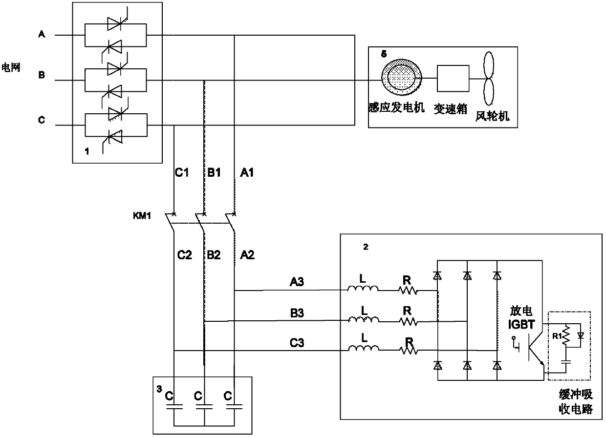
[0056] In order to suppress the overvoltage at the terminal of the wind turbine, in this embodiment, on the basis of Embodiment 1 or Embodiment 2, a lightning arrester is connected in parallel between the contactor and the parallel capacitor, such as Figure 4 (Taking the form of the active absorption circuit of Embodiment 1 as an example) as shown. When the terminal of the wind turbine is overvoltage, the lightning arrester is connected to the ground to avoid overvoltage at the terminal of the wind turbine and burn out the hardware. The arrester is placed in the circuit and connected to the three-phase contactor through the power lines A2, B2, and C2. The reactive power compensation capacitor and the active power absorption circuit are connected to the power lines A2, B2, and C2 through the power lines A3, B3, and C3. Other control methods for the circuit are the same as those in Embodiment 1 or Embodiment 2.


PUM


Abstract

The invention discloses a constant-speed constant-frequency wind turbine low voltage riding-through device and a control method, wherein the device comprises a network system and access switches connected in series between wind turbines; a contactor and a reactive power compensation module which are connected in series are in parallel connection between one switch and one wind turbine; an active power absorbing loop is connected in parallel between the contactor and the reactive power compensation module; and the switches are electronic switches. When the network system is in voltage sag, the switches are cut off, passages of the wind turbines, for feeding active power to the system, are cut off, the active power absorbing loop absorbs active power sent out by the wind turbines, and the reactive power compensation module compensates reactive power required by normal running of the wind turbines. The invention plays a role of restraining influences brought by voltage sags of the network system to the wind turbines, simultaneously enhances the reliability of power supply of a wind plant, and can reduce conditions that fans in the same wind turbine are forced to be cut off completely due to voltage sag of the network system, the practicability is strong, and great economic benefits are brought.

Description

Technical field: [0001] The invention relates to the field of power systems, in particular to a low-voltage ride-through device and a control method for constant-speed and constant-frequency wind turbines. Background technique: [0002] With the rapid development of wind power technology and the emphasis on renewable energy power generation in policies around the world, wind power has entered a period of rapid development. The unit capacity of wind turbines, the scale of wind farms and the share of wind power in the power system are all gradually increasing. The integration of large-scale wind power into the power grid has a certain impact on the planning, construction, operation scheduling, analysis and control, economic operation and power quality of the power grid. In order to promote the orderly development of wind farms and ensure the safe and stable operation of the power system, some power associations or power grid companies in Europe, North America, Australia and o...

Claims


Application Information

Patent Timeline
Patent Type & Authority Applications(China)
IPC IPC(8): H02J3/38H02J3/18H02P9/10
CPCY02E10/763Y02E40/30Y02E10/76
Inventor 王轩渠学景赵士硕王学军王柯韩天绪武丹杨武帝李志伟
Owner CHINA EPRI SCIENCE & TECHNOLOGY CO LTD
Why Eureka
Try Eureka