Nitrogen gas injection apparatus

A technology of nitrogen and injection holes, applied in mechanical equipment, electrical components, flange connections, etc., can solve problems such as complex processes, difficulties, and rising production costs, and achieve the effect of facilitating manufacturing, facilitating production, and promoting flow

Inactive Publication Date: 2012-07-11
李承龙
View PDF4 Cites 1 Cited by
  • Summary
  • Abstract
  • Description
  • Claims
  • Application Information

AI Technical Summary

Problems solved by technology

Therefore, the process of manufacturing the conventional nitrogen supply device becomes complicated, which increases the production cost
In addition, it is not easy to form a plurality of fine injection holes 22 on the thick body 21 of the flange tube 2, so it is difficult to inject nitrogen uniformly.
[0011] In addition, conventional nitrogen supply devices cannot easily finely control the injection of nitrogen gas, so it is difficult to install the device on the exit side of the vacuum tube of the process chamber
In this case, if an electronic flow control device can be used to control the amount of nitrogen supplied, the product price will inevitably increase
[0012] In addition, the flow of by-product gas is disturbed by the injection of nitrogen
Therefore, it is difficult to install the device on the outlet side of the vacuum line of the process chamber, which is sensitive to pressure changes
Also, since the injection hole 22 is blocked by the by-product gas, it is difficult to inject nitrogen uniformly

Method used


Image

  • Nitrogen gas injection apparatus
  • Nitrogen gas injection apparatus
  • Nitrogen gas injection apparatus

Examples


Embodiment Construction

[0038] Preferred exemplary embodiments of the present invention will be described below with reference to the accompanying drawings.

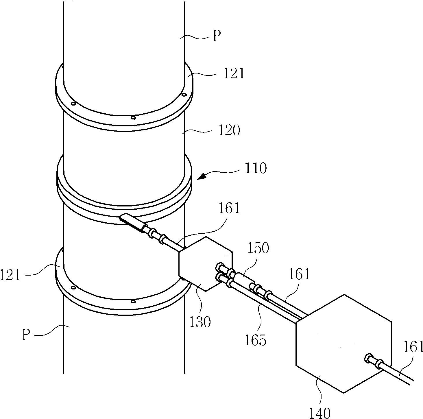
[0039] figure 2 Shown is an installation state diagram of a nitrogen injection device according to the present invention.

[0040] As shown, the nitrogen injection device of the present invention can be selectively installed on any pipe P at the outlet side of the process chamber, at the inlet or outlet side of a vacuum pump, or at the inlet or outlet side of a scrubber. The nitrogen injection device of the present invention can be easily installed in each pipe P, and the direction of nitrogen injection is controlled to be the same as the flow direction of the by-product gas, thereby facilitating installation in the exhaust pipe of the vacuum pump, the exhaust pipe of the scrubber, and the process chamber The vacuum tube on the outlet side of the chamber will not affect the vacuum level during the process.

[0041] As mentioned above, in the...


PUM


Abstract

The present invention relates to a nitrogen gas injection apparatus for semiconductor fabrication equipment of LCD fabrication equipment, which can be simply manufactured and which thus reduces manufacturing costs, and which enables a nitrogen gas injection direction to correspond to the flow direction of reaction by-products, to thereby inject nitrogen gas in an effective manner without disturbing the flow of reaction by-products. The nitrogen gas injection apparatus comprises: a pair of flanged pipes having flanges; a ring-shaped injection nozzle coupled along the inner wall of one of the flanged pipes coupled together, to supply nitrogen gas into the flanged pipes; and a nitrogen supply line connected to the injection nozzle to supply nitrogen gas.; The interior of the injection nozzle has a hole to enable the nitrogen gas supplied in a circumferential direction to flow, and a plurality of injection holes communicating with the hole to inject the supplied nitrogen gas into the flanged pipes. The injection holes are formed at the position protruding from the inner surface of one of the flanged pipes to inject nitrogen gas in the flow direction of reaction by-products.

Description

technical field [0001] The present invention relates to a semiconductor device and LCD manufacturing equipment, and more particularly, to a nitrogen gas injection device which can be easily manufactured with low production cost, and controls a nitrogen gas injection direction to coincide with a by-product flow direction, so that it can be efficiently injected Nitrogen without interfering with the flow of by-product gases. Background technique [0002] Generally, a semiconductor production process includes a manufacturing process and an assembly and testing process. The manufacturing process is the process of manufacturing semiconductors by depositing thin films on a wafer in various processing chambers and selectively and repeatedly etching the deposited films to form a predetermined pattern. The assembly and test process is a process of separating the chips produced in the manufacturing process individually, and then coupling the individual chips to a lead frame so as to b...

Claims


Application Information

Patent Timeline
Patent Type & Authority Applications(China)
IPC IPC(8): H01L21/02
CPCH01L21/67017F16L23/006H01L21/205H01L21/02H01L21/3065
Inventor 李承龙
Owner 李承龙
Why Eureka
Try Eureka