Frequency offset correction

一种基准频率、频率发生器的技术,应用在功率的自动控制、多个站之间的通信、电气元件等方向,能够解决影响终端成本、多空间、可用且可靠的晶体价格高等问题,达到减少同步时间、减少开发成本、增加精度的效果

Inactive Publication Date: 2012-07-11
ST ERICSSON SA
View PDF3 Cites 7 Cited by
  • Summary
  • Abstract
  • Description
  • Claims
  • Application Information

AI Technical Summary

Problems solved by technology

[0017] This circuit presents additional costs in terms of materials and development
Furthermore, the circuits take up more space on the silicon of a complete telecommunication circuit, contrary to the increasing miniaturization of circuits
[0018] Moreover, such deviation characteristics are available and reliable crystals are expensive, which affects the cost of the terminal

Method used


Image

  • Frequency offset correction
  • Frequency offset correction
  • Frequency offset correction

Examples


Embodiment Construction

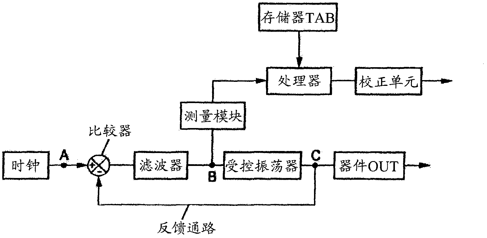
[0041] A circuit according to an embodiment of the invention is in figure 1 shown schematically. This circuit comprises a comparator COMP having an input A connected to the output of the clock CLK of the circuit and another input provided by the feedback path FEED. The output of this comparator is connected to the input of a low-pass filter FILTR whose output B is connected to the input of a controlled oscillator OSC, for example a voltage-controlled oscillator. The output terminal C of the controlled oscillator is connected to the feedback path and various devices OUT, and the various devices OUT receive radio frequency signals output from the controlled oscillator. The feedback path may include a frequency divider, which is not shown.

[0042] The component formed by the comparator, filter, oscillator, and clock-related feedback loop is called a phase-locked loop. Such loops are commonly used to control frequency in various electronic circuits. Typically, the input of th...


PUM


Abstract

The invention relates to a radio-frequency circuit comprising: - a control unit; and - a phase-locked loop; wherein the control unit is arranged to determine an offset between an actual value of a reference frequency at the input to the loop on the basis of a measurement of the signal output from the filter of the loop, and a theoretical value of said frequency known to the control unit, via a relation known to the control unit, and to control a correction of said offset.

Description

technical field [0001] The present invention relates generally to the field of integrated circuits used in the field of wireless communications. [0002] More particularly, it relates to estimating a frequency offset between an actual reference clock frequency and a theoretical reference clock frequency, which frequency offset may occur in circuitry of a wireless communication terminal. [0003] The invention finds particular application in integrated circuits equipping mobile radiotelephone equipment. Background technique [0004] There is a problem of inaccuracy in the ratio between the real value of the clock frequency of the wireless communication terminal and the carrier frequency of the signal it receives. Terminals must be precisely synchronized to the frequency of the electromagnetic waves used to carry communication signals in a wireless communication network. [0005] Offset can be caused by various reasons. For example, changes in temperature in a circuit or ag...

Claims


Application Information

Patent Timeline
Patent Type & Authority Applications(China)
IPC IPC(8): H03L7/06H04B7/26
CPCH03L7/06H04W56/00
Inventor 弗兰克・卡斯特克斯
Owner ST ERICSSON SA
Why Eureka
Try Eureka