Ultrasound probe and ultrasound imaging device
A technology of ultrasonic and photographic devices, which is applied in ultrasonic/sonic/infrasonic diagnosis, acoustic diagnosis, infrasonic diagnosis, etc. It can solve problems such as radiation sound pressure and sensitivity degradation, and achieve the effect of suppressing response
- Summary
- Abstract
- Description
- Claims
- Application Information
AI Technical Summary
Problems solved by technology
Method used
Image

Examples
no. 1 Embodiment approach
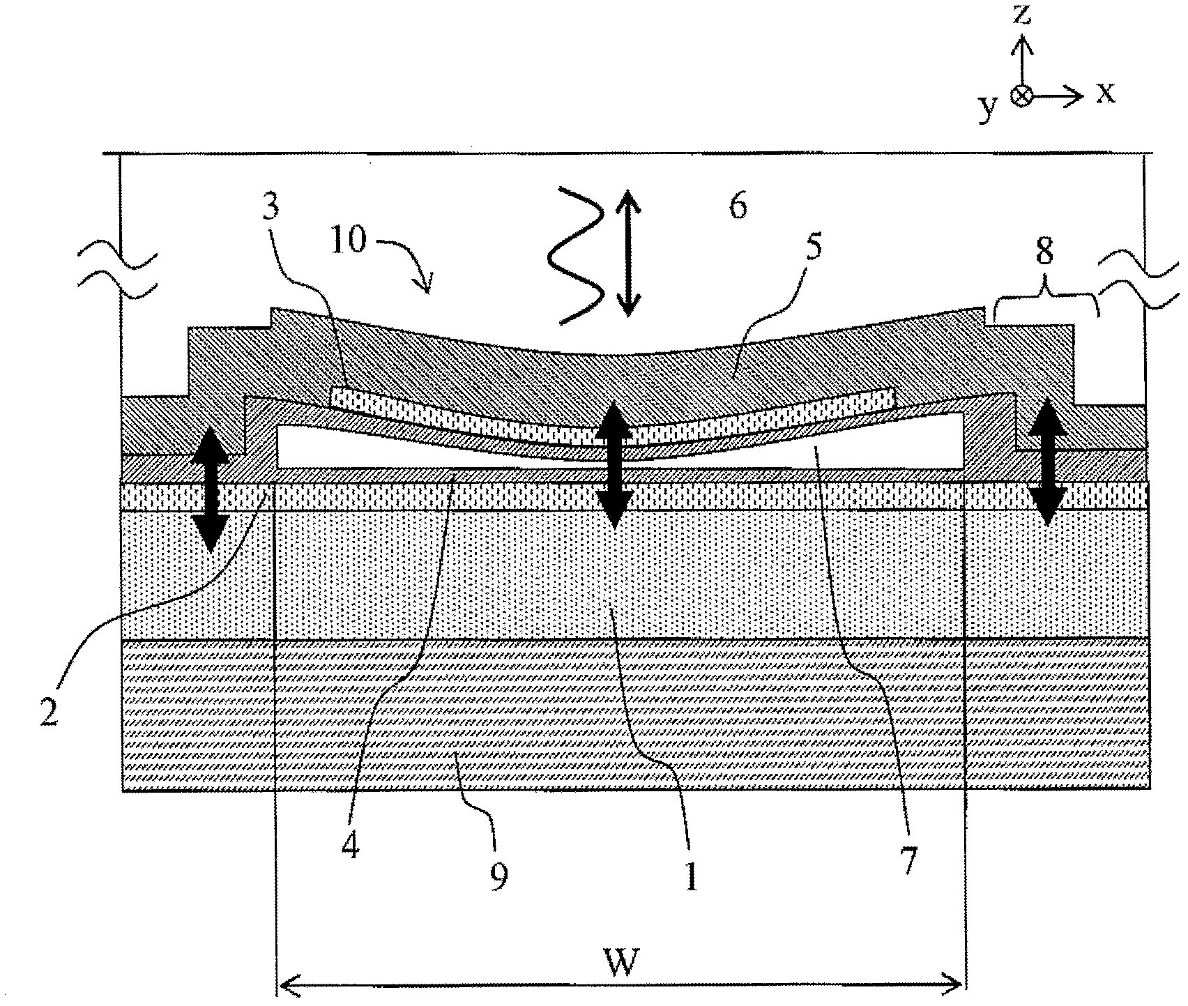
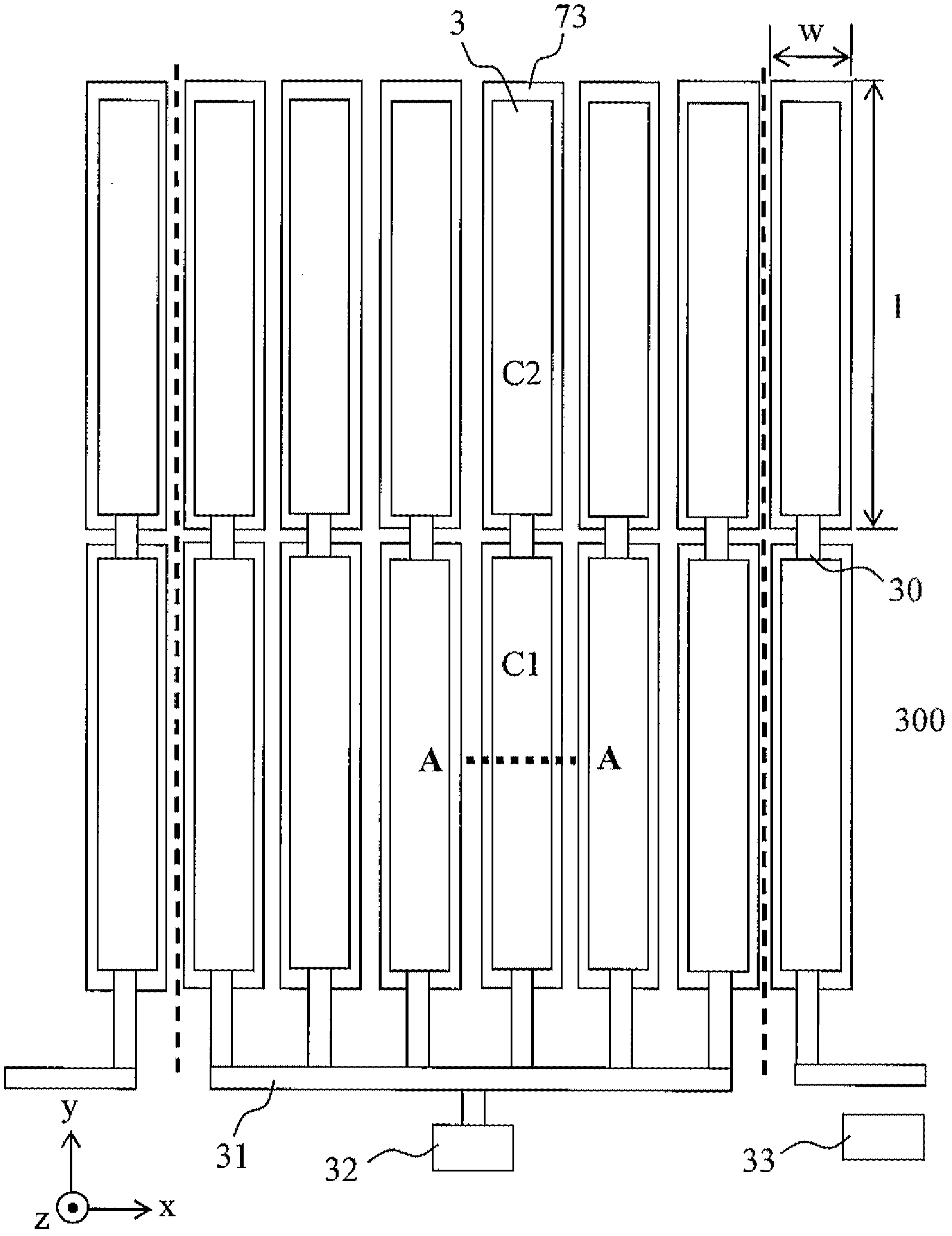
[0039] figure 1 It is a vertical sectional view of the CMUT (10) of the first embodiment, figure 2 is its top view. figure 2 The AA profile in figure 1 . In addition, for the convenience of description, the direction in which the CMUT (10) sends ultrasonic waves is figure 1 above and relative to figure 2 The vertical upward direction of the paper surface is set as the z direction. Additionally, the figure 1 and figure 2 The right-hand direction of is set to the x direction, which will be relative to figure 1 paper vertically downward direction and figure 2 The up direction of is set to the y direction.
[0040] Such as figure 1 and figure 2 As shown, in this CMUT (10), a thin-film lower electrode 2 made of a conductor such as aluminum or tungsten is formed on a flat substrate 1 made of an insulator such as single crystal silicon or a semiconductor, and a vibration is formed on the lower electrode 2. Film 5. Sometimes the silicon substrate also serves as the ...
no. 2 Embodiment approach
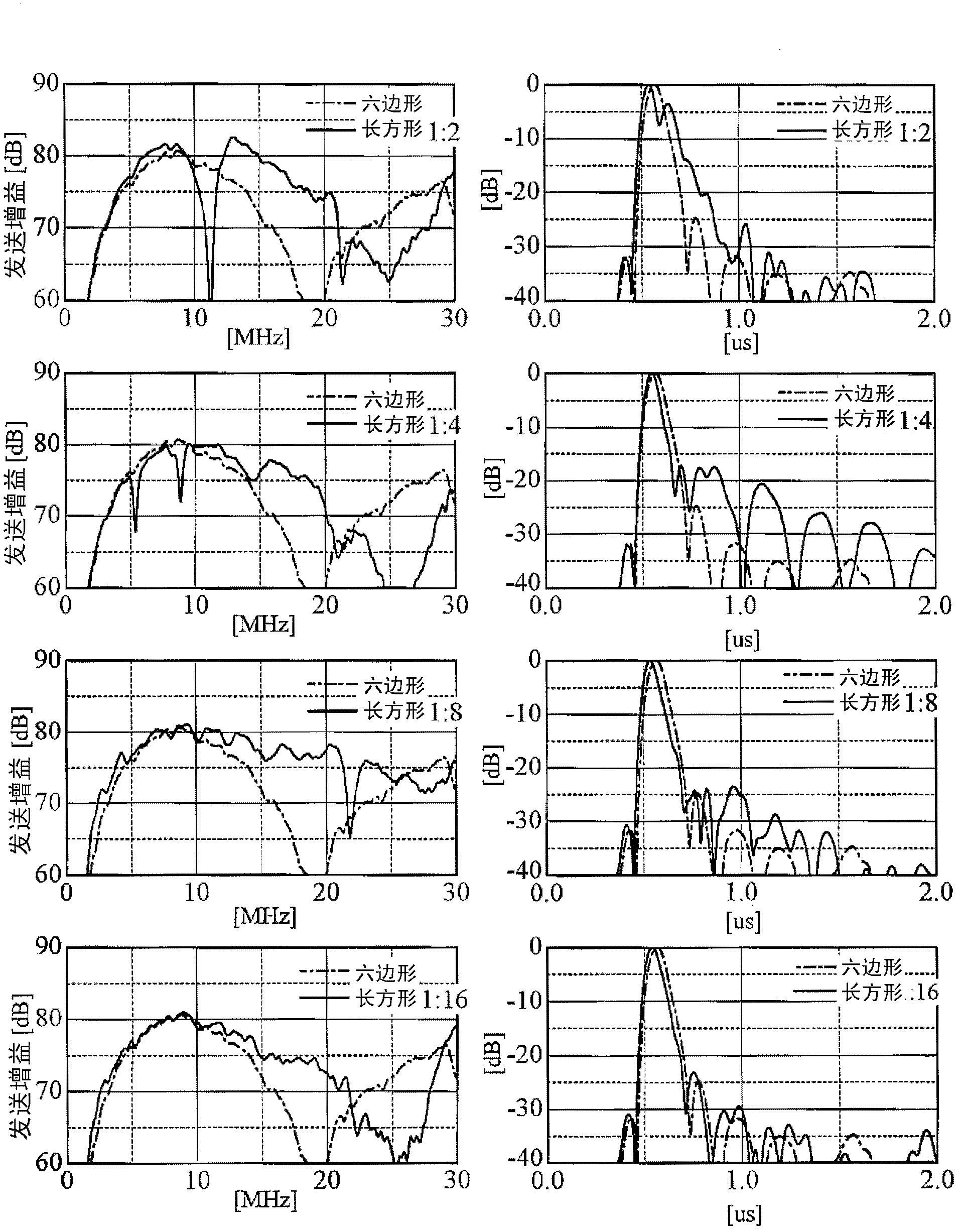
[0060] Figure 11 Not only the frequency characteristic is shown, but also the envelope of the time response of the transmitted sound waves. In an ultrasonic imaging device or the like, the width of the envelope has a large influence on the resolution of the image. Therefore, the width of the envelope becomes an important evaluation factor. When the aspect ratio is small and dip is large, the signal level after the main pulse is higher than in the case of hexagonal microcapsules, and so-called ringing (tailing: tailing) occurs. When such ringing occurs, it may become a noise component when imaging in an ultrasonic diagnostic apparatus or the like. Therefore, it is necessary to have a waveform in which ringing is reduced as much as possible for practical use. Depend on Figure 11 It can be seen that when the aspect ratio is "8" or more, the ringing level is almost the same as that of the hexagonal microcapsule (about -25dB or less).
[0061] Usually, the dynamic range of t...
no. 3 Embodiment approach
[0064] In the second embodiment, the frequency and depth are set according to a specific application, but the conditions can be changed for other applications. For example, even with the aim of photographing the same organism, a higher frequency can be used to photograph a shallower area with high resolution. At this time, in the case of capturing images up to about 3 cm at 20 MHz, the minimum necessary dynamic range is 0.5 [dB / cm / MHz] x 3 [cm] x 2 x 20 [MHz] = 60 dB. Depend on Figure 11 From the results, it can be seen that the ringing level of the transmission gain when the aspect ratio is "16" is about -30dB. That is to say, in the process of sending and receiving, it is equivalent to a DE of about 60dB. Therefore, it can be said that the aspect ratio of the rectangle under this condition is "16" or more.
[0065] Summarizing the above, it can be seen that in a more general case, the setting method of the aspect ratio can be specified as follows. Based on experimental ...
PUM
 Abstract
Description
Claims
Application Information