Airlift air stirring multi-sublayer circulating extraction device and method

An air stirring and extraction device technology, applied in the direction of liquid solution solvent extraction, etc., can solve the problems of lack of uniform mixing, insufficient power, and inability to circulate, etc., and achieve the effect of meeting industrial mass production, low power consumption, and low speed requirements

Inactive Publication Date: 2012-07-18
INST OF PROCESS ENG CHINESE ACAD OF SCI
View PDF7 Cites 6 Cited by
  • Summary
  • Abstract
  • Description
  • Claims
  • Application Information

AI Technical Summary

Problems solved by technology

[0007] However, when the above-mentioned reactor is applied to the extraction of different phases, the disadvantages of this structure are: first, because the light phase has a small amount and a large density difference compared with the liquid in the original system, a part of the light phase during the blowing process The phase can only float on the heavy phase, and cannot be completely circulated in the reactor, nor can it be broken, let alone evenly mixed, and the mass transfer effect in the reactor is extremely poor; secondly, since most of these reactors are open, The light phase is easily volatilized by the incoming gas, affecting the reaction
However, there are fewer sublayers formed during the dispersion process, resulting in insufficient power, so that the mixing and dispersion of the light phase in the heavy phase is not fast enough and thorough.
Especially for the disparity phase system, it is difficult to achieve complete mixing in a short time

Method used


Image

  • Airlift air stirring multi-sublayer circulating extraction device and method
  • Airlift air stirring multi-sublayer circulating extraction device and method
  • Airlift air stirring multi-sublayer circulating extraction device and method

Examples


Embodiment 1

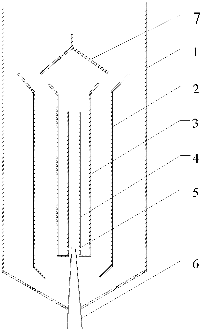
[0033] An air-lift air-stirred multi-layer circulation extraction device, such as figure 1As shown, it includes an outer tube 1 , an outer central tube 3 and an inner central tube 4 , and an inner tube 2 is installed between the outer tube 1 and the outer central tube 3 . An air intake pipe 6 is provided at the bottom of the outer pipe 1; the air intake pipe 6 leads into the inner central pipe 4. The tubes are connected by three support plates to maintain proper spacing between the tubes. The outer central pipe 3 is connected with the lower end of the inner central pipe 4 with a ring seal, and the inner central pipe 4 is provided with a plurality of air inlets 6 at a certain height from its bottom. An arc-shaped baffle 7 is arranged on the top of the inner central tube 4 and the outer central tube 3 , and its diameter is slightly larger than that of the outer central tube 3 .

Embodiment 2

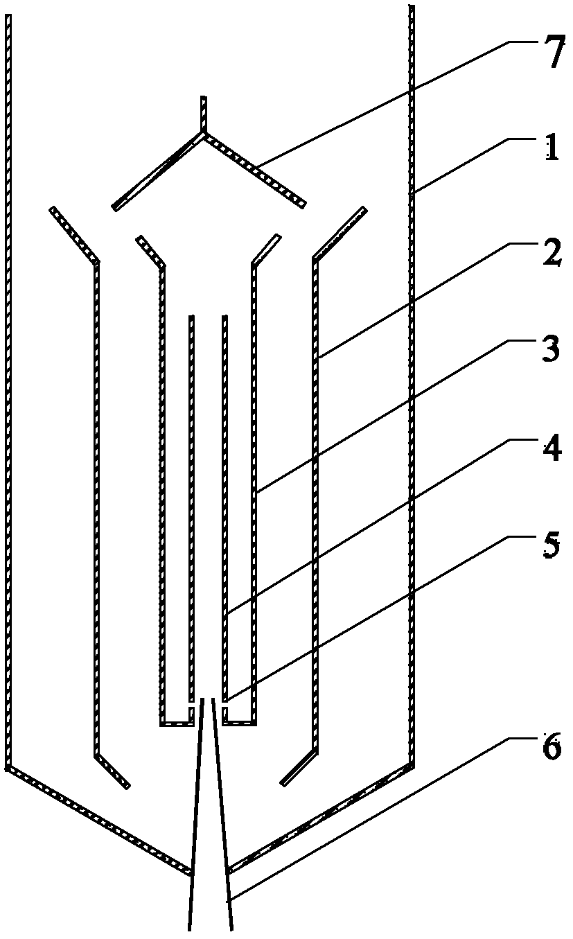
[0035] An air-lift air-stirring multi-layer circulation extraction device, comprising an outer tube 1, an outer central tube 3 and an inner central tube 4, the outer tube 1 is equipped with a thinner inner tube 2, and the inner tube 2 is equipped with a thinner inner tube The outer center tube 3 is equipped with a thinner inner center tube 4 inside the outer center tube 3 . An air intake pipe 6 is provided at the bottom of the outer pipe 1; the air intake pipe 6 leads into the inner central pipe 4. The tubes are connected by five support plates to maintain proper spacing between the tubes. The outer central pipe 3 is connected with the lower end of the inner central pipe 4 with a ring seal, and the inner central pipe 4 is provided with a plurality of air inlets 6 at a certain height from its bottom. An arc-shaped baffle 7 is arranged on the top of the inner central tube 4 and the outer central tube 3 , and its diameter is slightly larger than that of the outer central tube 3 ...

Embodiment 3

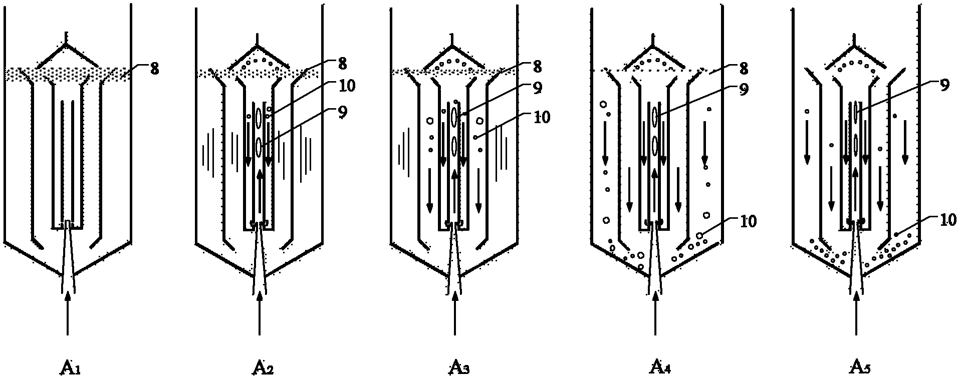
[0037] A kind of air lift type air stirring multi-layer circulation extraction method, such as figure 2 As shown, first add the mixed liquid to be extracted into the extraction device, and then add the light phase 8; after the ventilation starts, bubbles 9 are generated in the inner center tube 4, and a small cycle of the light phase 8 being sucked down is carried out between the two center tubes, and the light phase 8 is lightly absorbed at the same time. The phase 8 is broken; then the liquid in the inner and outer tubes starts to participate in the circulation one after another, and the light phase 8 is further broken; after a period of time, the light phase droplets 10 are completely mixed with the mixed liquid phase, and a stable multi-layer circulation begins to form.

[0038] The device of the present invention is combined with an air-lift air-stirred reactor disclosed in the prior patent CN 2403494Y to carry out the mixing operation of the light phase in the heavy phas...


PUM


Abstract

The invention relates to an airlift air stirring multi-sublayer circulating extraction device and an airlift air stirring multi-sublayer circulating extraction method. The device comprises an outer pipe, an outer center pipe and an inner center pipe; and an inner pipe is arranged between the outer pipe and the outer center pipe. The method comprises the following steps: firstly, mixed solution to be extracted is added into the extraction device and then a light phase is added; after the filling of the air is started, air bubbles are generated in the inner center pipe, the small circulation of sucking down the light phase is carried out between the two center pipes and simultaneously the light phase is crushed; then the solution in the inner and the outer pipes starts to participate in circulation and the light phase is further crushed; and after a certain time, light phase drops are totally mixed with a mixed solution phase to form the stable multi-sublayer circulation. The airlift air stirring multi-sublayer circulating extraction device and the airlift air stirring multi-sublayer circulating extraction method are particularly suitable for the process of uniformly dispersing the light phase into a heavy phase in an intervallic phase ratio system which has an oil-water phase ratio of less than 1:1,000 and is easy to emulsify; the operation can be continuously carried out under the condition that the two-phase interface is clear; the emulsification phenomenon is avoided; the airlift air stirring multi-sublayer circulating extraction device and the airlift air stirring multi-sublayer circulating extraction method have low equipment investment, are easy to operate, have low power consumption and small shear force for the solution and are beneficial to keeping the activity of biomacromolecules.

Description

technical field [0001] The invention relates to a liquid-liquid two-phase solvent extraction device and method in the fields of medicine, metallurgy or biochemistry, in particular to an air-lift type air-stirred multi-layer circulation extraction device and extraction method, and in particular to a very different A multi-layer circulation extraction device and extraction method for an easily emulsified system. Background technique [0002] Solvent extraction technology is an important development branch of current green chemistry. It is a mass transfer separation process that uses a liquid extractant to treat immiscible two-component or multi-component solutions to achieve component separation. The extraction technology can choose the appropriate extraction system and process according to the separation object and process requirements, which has the characteristics of high selectivity, good separation effect, easy operation and strong adaptability. With the wide application...

Claims


Application Information

Patent Timeline
Patent Type & Authority Applications(China)
IPC IPC(8): B01D11/04
Inventor 邢慧芳杨良嵘黄焜刘会洲
Owner INST OF PROCESS ENG CHINESE ACAD OF SCI
Why Eureka
Try Eureka