Method for driving a plurality of flyers by using laser and implementation device

A laser-driven, flying piece technology, which is applied to laser welding equipment, welding equipment, metal processing equipment, etc., can solve the problems of laser-driven flying piece technology limitations and other issues

Inactive Publication Date: 2012-07-18
TIANJIN UNIV
View PDF6 Cites 9 Cited by
  • Summary
  • Abstract
  • Description
  • Claims
  • Application Information

AI Technical Summary

Problems solved by technology

However, the current laser-driven flyer technology can only emit single particles, which limits the application of laser-driven flyer technology

Method used


Image

  • Method for driving a plurality of flyers by using laser and implementation device
  • Method for driving a plurality of flyers by using laser and implementation device
  • Method for driving a plurality of flyers by using laser and implementation device

Examples


experiment example 1

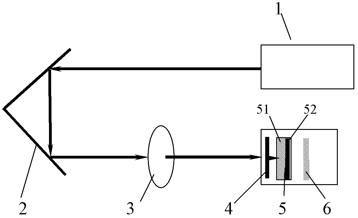
[0023] Quartz glass with a diameter of 40 mm and a thickness of 3 mm was ultrasonically cleaned with deionized water and absolute ethanol for 10 minutes to remove residual organic pollutants on the surface of the material, and then dried naturally in the air after cleaning. One surface of the cleaned quartz glass is coated with aluminum by magnetron sputtering, the purity of aluminum is 99.9999%, and the thickness of the obtained aluminum film is 6 μm. Using a nanosecond pulse laser, the laser light with certain parameters is diffracted by an orthogonal grating to produce a series of point lights, and each point light is incident on the flyer target made of optical glass deposited with a metal film, so that the metal film The surface evaporates, gasifies and ionizes instantaneously to generate high-temperature and high-pressure plasma. Due to the constraints of optical glass, the high-pressure shock wave generated by the plasma acts on the metal film in front of the incident ar...

experiment example 2

[0026] The difference between Experimental Example 2 and Experimental Example 1 is that aluminum is adhered to one surface of the cleaned quartz glass by the adhesive film method, and the thickness of the aluminum film is 20 μm. Set the distance between the flyer target 5 and the impact target 6 to be 4 mm. Choose laser energy 320mJ, trigger frequency 1Hz, laser pulse width 6ns.

experiment example 3

[0028] The difference between Experimental Example 3 and Experimental Example 1 is that a layer of graphite with a thickness of 6 μm is deposited on one surface of the cleaned quartz glass by pulling method, and then aluminum is adhered on the graphite film by the adhesive film method, and the thickness of the aluminum film is 20 μm. Set the distance between the flyer target 5 and the impact target 6 to be 6 mm. Choose laser energy 280mJ, trigger frequency 5Hz, laser pulse width 6ns.


PUM

PropertyMeasurementUnit
thicknessaaaaaaaaaa

Abstract

The invention discloses a method for driving a plurality of flyers by using laser. The method comprises taking a laser beam generated by a laser as incident laser which is split into a plurality of light beams by a beam splitter, emitting the light beams to the surface of a metal thin film which is adhered to or deposited on a piece of optical glass by using the optical glass to instantly evaporate, gasify and ionize the surface of the metal thin film and generate high-temperature high-pressure plasmas, and making high-pressure shock waves generated by the plasmas act on the metal thin film positioned in front of an incident area under the constraint of the optical glass so as to cut the residual metal thin film, and driving the residual metal thin film at high speed, thereby forming ultrahigh speed flyers. An integral laser wave is spatially split into a plurality of tiny focus array points by using an optical diffraction or refraction principle, and a plurality of particles with equal or unequal energy are driven at the same time by an optical beam splitter such as a cross grating, a micro lens array and the like to realize the multipoint driving emission of a single laser source.

Description

technical field [0001] The invention relates to a plasma driving acceleration method, in particular to a method for simultaneously driving multiple flyers by a single laser source by using a light splitting element and a device for realizing the same. Background technique [0002] Since Theodore Maiman of Hughes Laboratory in California realized the first laser beam in 1960, the interaction process, mechanism and application of laser and materials have been favored by researchers. In the early 1990s, humans first proposed the concept of laser drive, intending to launch small satellites into low-earth orbit through ground-based continuous high-frequency lasers. [0003] Laser drive is the use of laser to propel the material to fly at high speed. It has a wide range of applications: laser-controlled nuclear fusion, active removal of space junk, laser-driven rockets or "photon rocket" technology, and laser-driven flyers. [0004] Laser-driven flyer is a dynamic high-voltage l...

Claims


Application Information

Patent Timeline
Patent Type & Authority Applications(China)
IPC IPC(8): B23K26/00B23K26/064B23K26/067B23K26/18
Inventor 魏强宋丽红平瑞婷
Owner TIANJIN UNIV
Why Eureka
Try Eureka