
Excircle cavity opening type dynamic-static pressure main shaft unit

A dynamic and static pressure, main shaft technology, applied in the directions of shafts, bearings, shafts and bearings, can solve problems such as difficulty in ensuring shape tolerance and position tolerance, difficulty in processing dynamic and static pressure bearings, and difficulty in ensuring position, so as to improve labor productivity and ease of use. The effect of processing and reducing the difficulty of processing

Active Publication Date: 2012-07-18
SHANDONG BEST PRECISION
View PDF5 Cites 5 Cited by
  • Summary
  • Abstract
  • Description
  • Claims
  • Application Information

AI Technical Summary

Problems solved by technology

[0004] However, due to the difficulty in processing the dynamic and static pressure bearings, there are the following technical difficulties: (1) The special performance of the dynamic and static pressure spindle unit requires the bearing to be a thin-walled copper sleeve with a soft material, and several oil chambers are opened on the inner circle of the copper sleeve, but The material of copper is very soft and the wall is thin, and the clip is easily deformed during processing. It is difficult to ensure the shape tolerance and position tolerance between the cavities, as well as the coaxiality of the inner and outer circles and the roundness of the inner hole; (2) the outer circle of the copper sleeve must be Drill a small hole of 0.6-1mm at the precise position to feed oil, the small hole is difficult to process and the position is not easy to guarantee

Method used


Image

  • Excircle cavity opening type dynamic-static pressure main shaft unit
  • Excircle cavity opening type dynamic-static pressure main shaft unit
  • Excircle cavity opening type dynamic-static pressure main shaft unit

Examples


Embodiment Construction

[0016] In order to clearly illustrate the technical characteristics of this solution, the following implementation examples illustrate this solution.

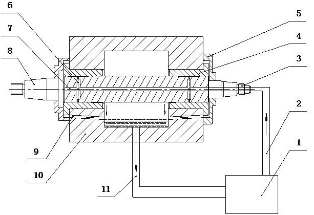
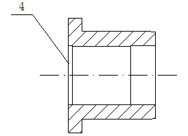
[0017] See figure 1 , figure 2 with image 3 , The present invention is an external open cavity type dynamic and static pressure main shaft unit, including a dynamic and static pressure main shaft 8, a dynamic and static pressure bearing 4 and an oil supply system, wherein the hydrostatic and dynamic pressure main shaft 8 is provided with several circumferentially evenly distributed oil cavities on the outer cylindrical surface of the journal; The oil cavity is composed of a deep cavity 13 and a shallow cavity 12. The radial cross section formed by the deep cavity 13 and the shallow cavity 12 is stepped; the dynamic and static pressure spindle 8 is provided with an axial oil inlet 7 and the journal of the dynamic and static pressure spindle 8 A radial oil outlet hole 6 communicating with the axial oil inlet hole 7 is provided, an...


PUM


Abstract

The invention provides an excircle cavity opening type dynamic-static pressure main shaft unit. The excircle cavity opening type dynamic-static pressure main shaft unit comprises a dynamic-static pressure main shaft, a dynamic-static pressure bearing and an oil supply system, wherein the shaft neck excircle cylindrical surface of the dynamic-static pressure main shaft is provided with a plurality of oil chambers which are uniformly distributed circumferentially. The dynamic-static pressure main shaft unit provided by the invention has the beneficial effects that as the dynamic-static pressure main shaft is made of steel, the oil chambers can be more conveniently arranged on the excircle cylindrical surface of the dynamic-static pressure main shaft than on the inner wall of the dynamic-static pressure bearing, and are easy to process, thereby greatly reducing processing difficulty, saving cost, and improving labour productivity; and the dynamic-static pressure main shaft unit not only has the advantages of small original static pressure support driving power and the like compared with the traditional dynamic-static pressure main shaft unit, but also reduces start power consumption and prolongs the service life of the bearing, thereby increasing the reliability and overload resistance capacity of the bearing.

Description

Technical field [0001] The invention relates to a dynamic and static pressure main shaft unit, in particular to an external circular cavity type dynamic and static pressure main shaft unit. Background technique [0002] The hydrodynamic and hydrostatic hybrid bearing is a high-tech product developed in the 1980s in my country with the world's advanced level. It is a new type of movable bearing that not only integrates the advantages of hydrodynamic and hydrostatic bearings, but also overcomes the shortcomings of the two. It can be used for the transformation of old machine tools as well as for new machine tools. The use of dynamic and static pressure bearings can completely restore the precision and surface roughness of the machine tool due to the spindle bearing problem; improve the accuracy and cutting efficiency of the machine tool spindle. Over the years, some Chinese enterprises have adopted dynamic and static pressure bearings for new machine tools as well as reformed dome...

Claims


Application Information

Patent Timeline
Patent Type & Authority Applications(China)
IPC IPC(8): F16C32/06F16C3/02
Inventor 葛慧颖朱继生李鄄高修前
Owner SHANDONG BEST PRECISION
Learn More