Method for launching marine controlled-source electromagnetic exploration system

An exploration system and electromagnetic technology, applied in the direction of electric/magnetic exploration, radio wave measurement system, sound wave reradiation, etc., can solve problems such as excessive cable requirements, poor system stability, and large loss

Inactive Publication Date: 2012-07-18
BEIJING UNIV OF TECH
View PDF1 Cites 15 Cited by
  • Summary
  • Abstract
  • Description
  • Claims
  • Application Information

AI Technical Summary

Problems solved by technology

At present, the main shortcomings of the controllable source electromagnetic prospecting and launching methods dominated by these two companies are that the cable requirements are too high in t

Method used


Image

  • Method for launching marine controlled-source electromagnetic exploration system
  • Method for launching marine controlled-source electromagnetic exploration system
  • Method for launching marine controlled-source electromagnetic exploration system

Examples


Example Embodiment

[0033] Example 1:

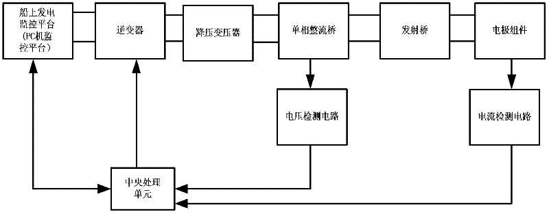
[0034] Such as figure 1 As shown, the specific implementation of the hardware circuit of the present invention is as follows:

[0035] The generator set in the system provides a 3-phase unstable power supply with a power of 30KVA, a frequency of 50HZ and a voltage of 380V for the system. The above-mentioned power supply is boosted by a step-up transformer with a ratio of 1:4, and then rectified and filtered by a three-phase rectifier bridge. Obtain a single-phase DC power supply with a frequency of 50HZ and a voltage of 2000±10%V; the above-mentioned single-phase DC power supply is sent to the seabed 4Km deep through the towing cable, and then the underwater part of the system receives the power through the inverter The single-phase DC power supply is inverted into single-phase AC with a frequency of 20KHZ, and then reduced by a step-down transformer with a transformation ratio of 18:1 to obtain an AC voltage with a frequency of 20KHZ and an amplitude voltage of...

Example Embodiment

[0037] Example 2:

Example Embodiment

[0038] Such as figure 1 The specific implementation of the hardware circuit of the present invention is as follows:

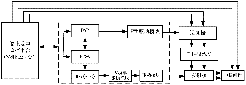
[0039] The invention is divided into three parts: the onboard power generation monitoring platform of the system, the towing cable and the underwater part of the system. The system’s shipboard power generation monitoring platform includes generator sets, step-up transformers, three-phase rectifier bridges, and PC monitoring platforms; the towing cables are transmission cables; the underwater part of the system includes inverters, step-down transformers, single-phase rectifier bridges, and transmitters. Bridge and electrode assembly. Among them, the output port of the generator set is connected to the input port of the step-up transformer; the output port of the step-up transformer is connected to the input port of the three-phase bridge rectifier, the output port of the three-phase bridge rectifier is connected to the input port of the towing cable, and the output...


PUM


Abstract

The invention relates to a method for launching a marine controlled-source electromagnetic exploration system. One generator unit, two inverters, two rectifier and filter circuits, one control circuit, one voltage detection circuit, one current detection circuit as well as a tow cable and an electrode assembly are included, wherein the generator unit provides a three-phase power supply to the system; the inverter and rectifier circuits are used for finishing AC-DC and DC-AC conversions of the power supply in the signal transmission and emission process; the transformer is used for transforming voltage grade and is convenient for signal transmission and emission; the voltage detection circuit and the current detection circuit are used for realizing real-time detection of output voltage and current and provide real-time signals for the control circuit; and the control circuit is a central processing unit. According to the method for launching the marine controlled-source electromagnetic exploration system, disclosed by the invention, the signal transmission reliability of the system is improved, the requirement on the cable is reduced and the economic cost is reduced.

Description

technical field [0001] The invention relates to a launching method for a marine controllable source electromagnetic prospecting system, belonging to the technical field of marine electromagnetic prospecting. Background technique [0002] Seabed geophysical detection instruments are an important means of detecting marine mineral resources, and it is also a development trend in recent years. As an important branch of seabed geophysical detection instruments, marine controlled source electromagnetic exploration system plays a very important role in the exploration of deepwater oil and gas resources on the seabed. The marine controlled source electromagnetic prospecting system includes the marine controlled source electromagnetic prospecting transmitting system and the marine controlled source electromagnetic prospecting receiving system, among which the marine controlled source electromagnetic prospecting transmitting system is the core part of the whole prospecting system and ...

Claims


Application Information

Patent Timeline
IPC IPC(8): G01V3/00
CPCY02A90/30
Inventor 张一鸣余飞曾志辉刘燕楠陈东升
Owner BEIJING UNIV OF TECH
Why Eureka
Try Eureka