Ultra-high power transformer

A power transformer, ultra-high technology, applied in the direction of transformer/inductor cooling, transformer/inductor coil/winding/connection, etc., can solve problems such as transformer overheating, transformer thickness increase, coil thickness increase, etc.

Inactive Publication Date: 2012-07-18
YUJING TECH CO LTD
View PDF7 Cites 0 Cited by
  • Summary
  • Abstract
  • Description
  • Claims
  • Application Information

AI Technical Summary

Problems solved by technology

Due to the continuous advancement of technology and the demand for high brightness of LCD displays, some manufacturers have increased the number of lamps used in the backlight module of the LCD display, and the number of transformers used will also increase. In this way, Not only does it cause the volume of the liquid crystal display to become larger, but the relative weight also becomes heavier.
Therefore, some manufacturers will use a single transformer to drive multiple lamps. If the above-mentioned transformer is used to drive multiple lamps, the voltage of the transformer must be increased to match its high power output; therefore, using a single transformer to drive When there are multiple lamp tubes, the primary coil and the secondary coil are all wound on the same bobbin, so that the winding area of ​​the primary coil is limited. Therefore, if the voltage output is increased according to the needs of the transfo

Method used


Image

  • Ultra-high power transformer
  • Ultra-high power transformer
  • Ultra-high power transformer

Examples


Embodiment Construction

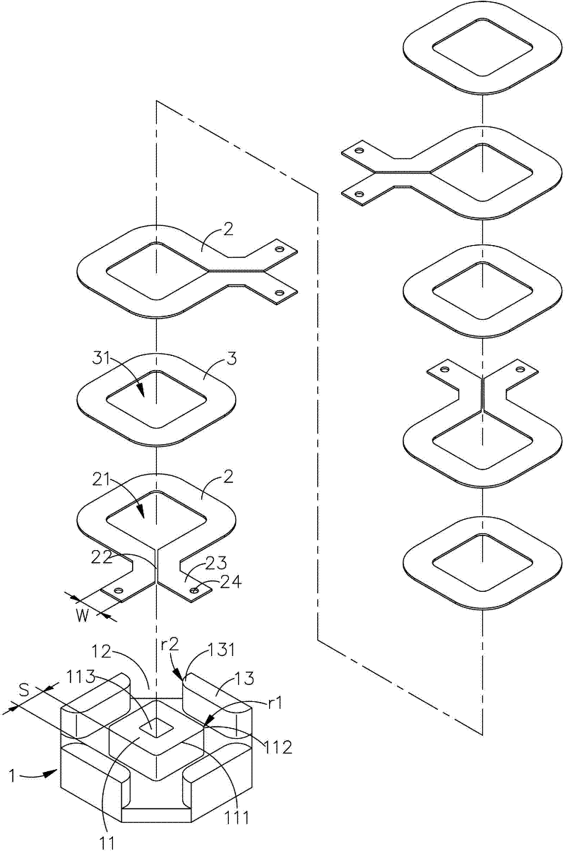
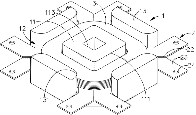
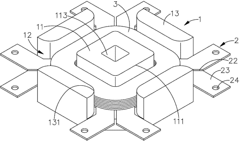
[0013] see figure 1 and figure 2 As shown, it is a schematic diagram of the three-dimensional structure decomposition and assembly of the preferred embodiment of the ultra-high power transformer of the present invention. The ultra-high power transformer of the present invention includes: a base 1 , a plurality of sheets 2 and a plurality of barriers 3 .

[0014] The base 1 further includes: a main core 11 , a plurality of slots 12 and a plurality of side wings 13 . The aforementioned main core portion 11 is a polygonal shape. In a preferred embodiment of the present invention, the aforementioned main core portion 11 is a square shape. Of course, this main core portion 11 can also be other such as pentagonal or hexagonal, etc. Changes like this can be implemented by those who are familiar with the art according to the above description, so they do not depart from the gist of the present utility model, nor depart from the spirit and scope of the present invention, so no more ...


PUM


Abstract

The invention provides an ultra-high power transformer, which comprises a base, a plurality of sheet bodies and a plurality of barrier bodies. The base comprises a main core part, a plurality of open grooves and a plurality of wing parts. The main core part is in a polygonal shape and the two edges thereof are provided with a first top corner of a first radius of curvature. The main core part is provided with a through hole penetrating the main core part. Each open groove corresponds to the top corner. Each wing part corresponds to the edges of the main core part. A gap is reserved between the wing part and the edge of the main core part. The wing part is provided with a second top corner of a second radius of curvature close to the above open groove. Each sheet body is provided with a through hole and a guide groove. The through hole is arranged in the main core part. The guide groove corresponds to the open groove.

Description

technical field [0001] The invention relates to the improvement of a transformer structure, in particular to an ultra-high power transformer used in large wattage (more than 3000 watts). Background technique [0002] Due to the rapid advancement of high-tech technology in recent years, especially in the field of microelectronics-related technology and manufacturing processes, electronic-related products have penetrated into every family and all walks of life and become an indispensable part of modern life. . [0003] A transformer traditionally used to drive the backlight module lamp inside a liquid crystal display (LCD), the transformer has a coil base with a primary line area and a secondary line area, and a plurality of terminals are provided at both ends for connecting the wires of the winding and soldered to the circuit board. Due to the continuous advancement of technology and the demand for high brightness of LCD displays, some manufacturers have increased the numbe...

Claims


Application Information

Patent Timeline
IPC IPC(8): H01F27/30H01F27/28H01F27/08
Inventor 潘正友
Owner YUJING TECH CO LTD
Why Eureka
Try Eureka