
Thermodynamic process control based on pseudo-density root for equation of state

A state equation and process control technology, applied in the system field, can solve problems such as impossible and difficult factory control

Inactive Publication Date: 2012-07-18
INVENSYS SYST INC
View PDF2 Cites 3 Cited by
  • Summary
  • Abstract
  • Description
  • Claims
  • Application Information

AI Technical Summary

Problems solved by technology

This heavy processing load challenges the ability to provide accurate data at a rate sufficient to obtain predictive models in a timely manner to pre-empt critical situations, making real-world plant control difficult or impossible

Method used


Image

  • Thermodynamic process control based on pseudo-density root for equation of state
  • Thermodynamic process control based on pseudo-density root for equation of state
  • Thermodynamic process control based on pseudo-density root for equation of state

Examples


Embodiment Construction

[0023] It should be understood at the outset that although an exemplary implementation of one or more embodiments is illustrated below, the disclosed systems and methods can be implemented using various techniques, whether presently known or in existence. The disclosure should in no way be limited to the exemplary implementations, drawings, and techniques illustrated below, but may be modified within the scope of the appended claims and all equivalents thereof.

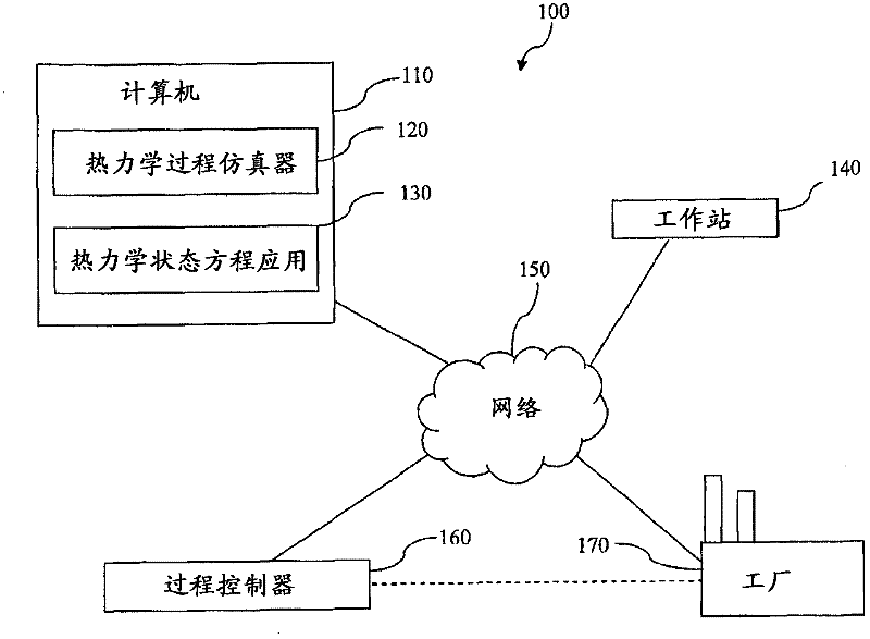
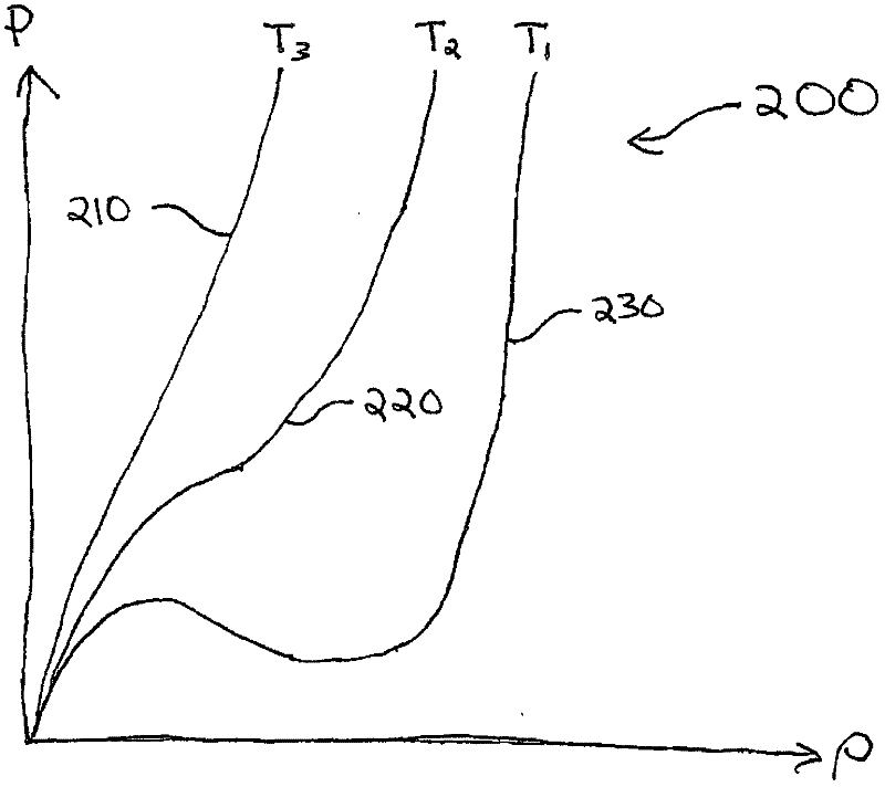
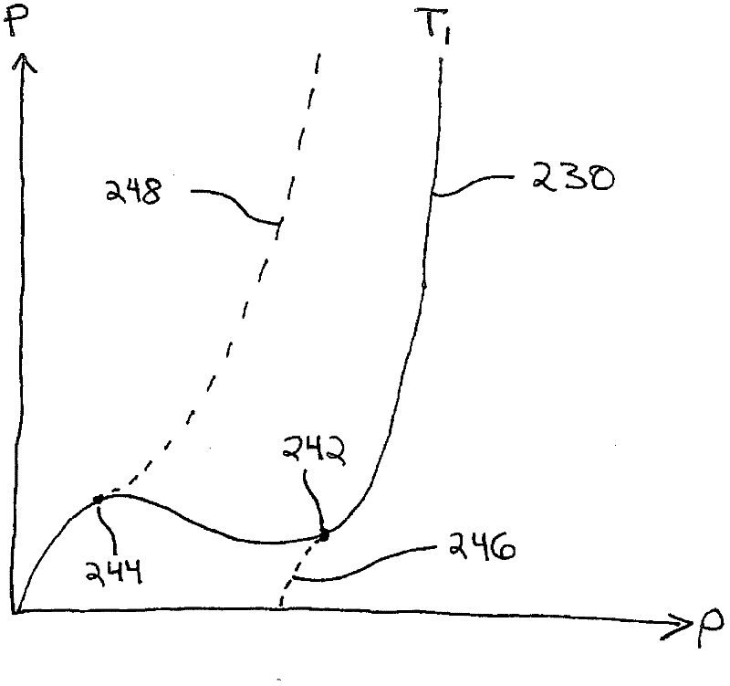
[0024] The present disclosure teaches a system and method of modeling and controlling a thermodynamic system. The method can be run on a computer to compute, thereby simulate and / or model properties of a thermodynamic system. The method includes determining pseudoproperties within arguments of a dynamically determined portion of a thermodynamic equation of state. Some equations of state can have In the form of , where EOS() represents the object state equation, where P represents pressure, T represents temperature,...


PUM


Abstract

A thermodynamic modeling system comprising a computer, a thermodynamic process simulation application, and a thermodynamic equation of state application is provided. The thermodynamic equation of state application determines a density root based on a first and second point of departure from an equation of state and based on a first and a second extrapolation equation. The first departure point satisfies the equation the partial derivative of pressure with respect to density equals a first constant times the pressure divided by the density plus a second constant. The density root is determined as a pseudo-density in a phase two when the specified pressure is greater than the second departure point pressure and in a phase one when the specified pressure is less than the first departure point pressure.; The thermodynamic process simulation application invokes the thermodynamic equation of state application to determine a result based on the density root.

Description

Background technique [0001] To continuously improve operational efficiency, industrial plants such as chemical plants, refineries, food processing plants, pharmaceutical plants, breweries, and other batch and continuous plant systems can employ computer-based modeling and simulation to optimize plant operations. These modeling systems are generally used to simulate a plant by defining the plant's components and equipment with computer models, and then using mathematical calculations to predict and / or reveal the behavior of these systems as relevant parameters vary. [0002] Such modeling can be used to aid in the design and operation of such plants by simulating the process and plant response to changes that would occur under real conditions, as well as to provide computer-based operator training without the risk of exposing plants to these The hazard or cost associated with the event. Additionally, plant behavior can be predicted to allow for strategies to deal with these ev...

Claims


Application Information

Patent Timeline
IPC IPC(8): G06F17/00G06F9/455G06F15/16
CPCG05B17/02
Inventor G·徐D·布拉克D·J·范伯尔森I·H·伯伊斯
Owner INVENSYS SYST INC
Learn More