Eureka AIR delivers breakthrough ideas for toughest innovation challenges, trusted by R&D personnel around the world.

Baseline-free computer embroidery machine

A computer and embroidery machine technology, applied in the field of computer embroidery machines, can solve the problems of poor production efficiency, extended rest time, high working hours and high cost, and achieve the effect of ensuring quality and making embroidery patterns or three-dimensional shapes more detailed

Inactive Publication Date: 2012-07-25
杨星源
View PDF11 Cites 13 Cited by
  • Summary
  • Abstract
  • Description
  • Claims
  • Application Information

AI Technical Summary

Problems solved by technology

[0004] However, the pattern or three-dimensional shape embroidered on the cloth of traditional embroidery is still carried out manually, so that the embroidery process requires experienced personnel to reach a certain level, and if the embroidery is used on clothes, business exhibitions or exposition company logos Embroidery of eye-catching patterns or other eye-catching patterns often requires the employment of many people to cope with a large number of production needs, which consumes a lot of man-hours and costs; in addition, in order to meet the customized needs of consumers, the embroidery process It is also relatively cumbersome and difficult, not only difficult to ensure a certain quality of embroidery, but also unable to achieve mass production of embroidery automation; in addition, in the process of manual embroidery, the repeated force and repetitive labor operation of the hands will easily cause fatigue. And it will lead to cumulative occupational injuries for a long time. In order to reduce the occurrence of occupational injuries, it is necessary to reduce the workload of personnel, extend the rest time and rearrange the operating procedures, resulting in poor production efficiency and not in line with economic considerations.
[0005] Furthermore, as the traditional embroidery industry continues to break through and innovate, various computer embroidery machines have been developed on the market. They have a machine base, and several embroidery stand-alone machines are arranged on the stand, and a rectangular embroidery machine is located below the embroidery stand-alone machine. Mobile frame, when the fabric is laid flat on the mobile frame, multiple clamps can be used to clamp the fabric on the periphery of the mobile frame in a tight state, and during the embroidery process, the embroidery stand-alone machine and the mobile frame will be controlled by a microcomputer. Control, to respond to the pattern or three-dimensional shape of the embroidery, the corresponding action can be driven by the transmission mechanism inside the embroidery stand-alone machine to rotate the thread hooker, and cooperate with the needle bar and thread hooker on the body to hook the bottom thread. Embroidery on fabrics, although it can be processed on fabrics to form continuous embroidery patterns or three-dimensional shapes, but due to the limited horizontal movement distance of the moving frame and the embroidery stand-alone machine, the length of the embroidery will be limited and it can only be used in Small-scale fabric embroidery operations, and because each embroidery machine can only perform vertical up and down embroidery movements, it is easy to be limited by the angle of specific embroidery stitches, and it cannot be refined, and it is difficult to ensure the overall quality of embroidery , and it needs to be redesigned by those engaged in this industry to effectively solve

Method used


Image

  • Baseline-free computer embroidery machine
  • Baseline-free computer embroidery machine
  • Baseline-free computer embroidery machine

Examples


Embodiment Construction

[0033] The features and functions of the present invention will be described in detail below in conjunction with the accompanying drawings and preferred embodiments of the present invention to facilitate a complete understanding.

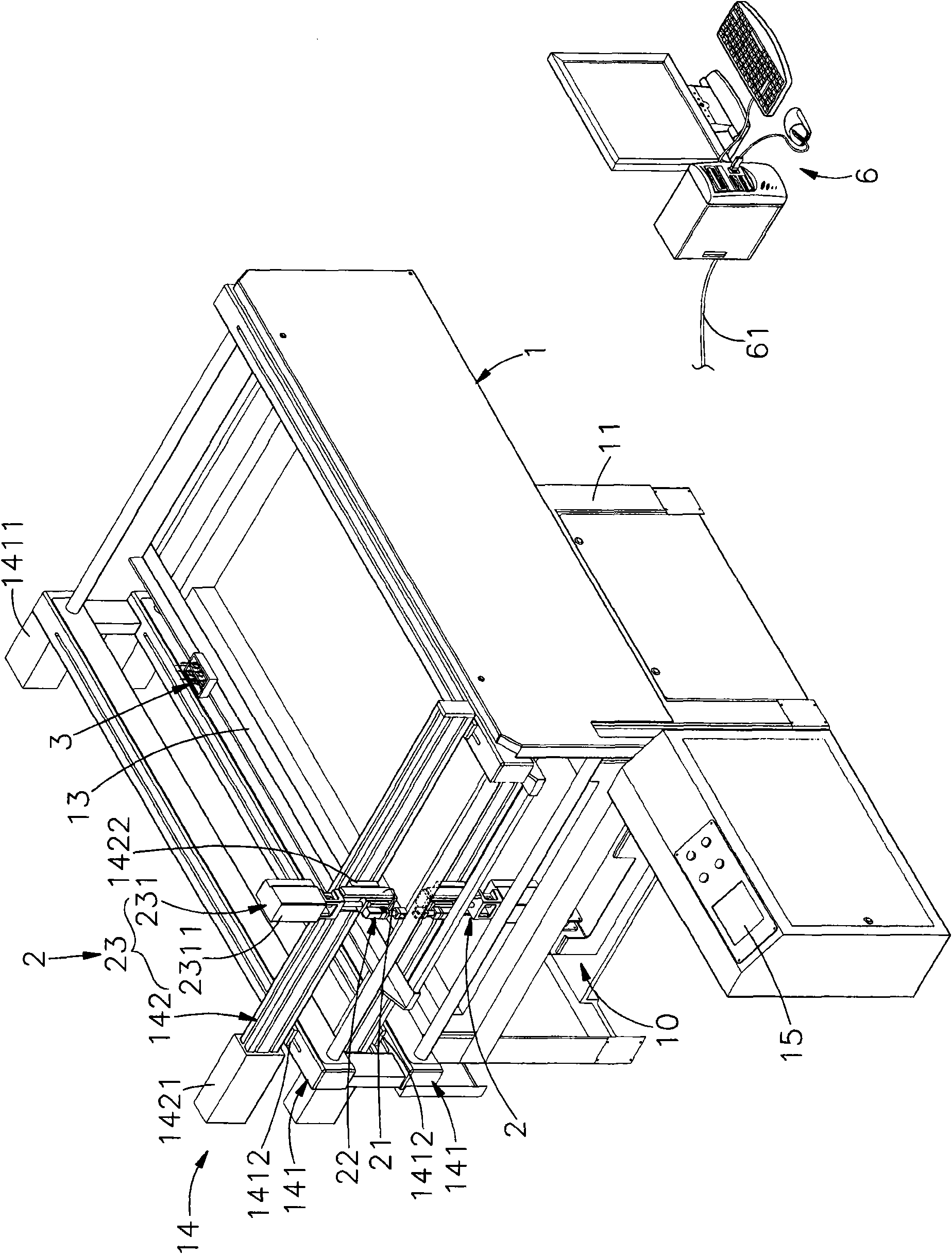
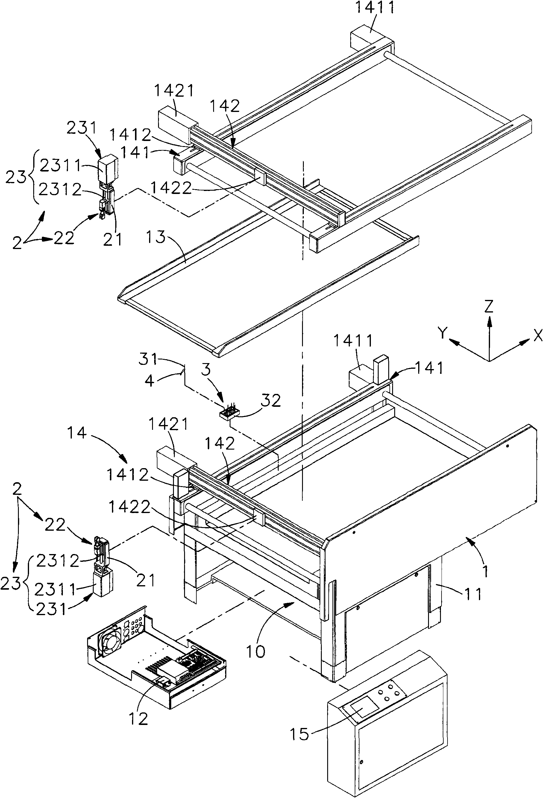
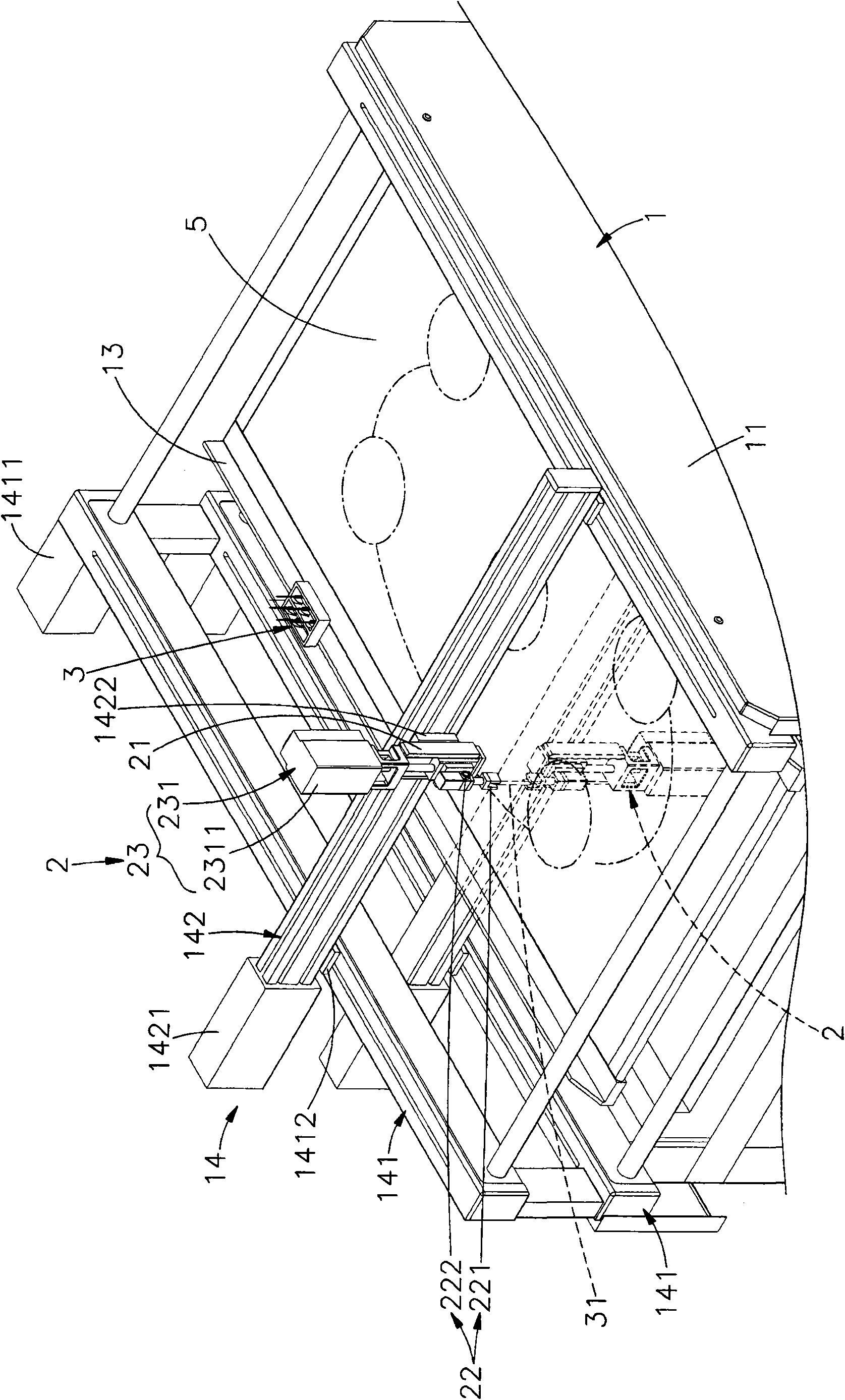
[0034] see figure 1 , 2 , 3 are respectively the three-dimensional appearance diagram, the three-dimensional exploded view and the three-dimensional appearance diagram of the preferred embodiment of the present invention. It can be clearly seen from the figure that the present invention includes an organic table 1, a plurality of embroidery machines and tools 2 and needlework equipment 3. The main components and features of the present invention are now described in detail as follows, wherein:

[0035] The machine table 1 has a base 11, and an accommodating space 10 for accommodating the control module 12 is formed inside the base 11, and a frame 13 is arranged above the base 11, and the base 11 is located around the frame 13, Two or more sets of ...


PUM


Abstract

The invention relates to a baseline-free computer embroidery machine. The pedestal of a machine table is provided with a frame for positioning a cloth, the pedestal positioned on the upper side and the lower side surrounding the frame is provided with two or more than two groups of driving devices back and forth moving in a biaxial or multiaxial linear or rotary direction to respectively combine supports of a plurality of embroidery facilities with the driving devices, so holders which are positioned on the upper side and the lower side of the frame and correspond with each other utilize an elevating device to drive the embroidery facilities to back and forth move in a vertical axial direction, and two clamping jaws of one holder, which are in an opposite clamping or opening state, cooperate the other holder to form a continuous embroidery pattern or a stereo model on the cloth through embroidering in a circulating needle pulling and embroidering manner by color threads threaded on embroidered needles according to preprogrammed mobile paths or a parameter-set tambour needle method. The machine of the invention has the advantages of convenient batch production, machining efficiency improvement and production cost reduction.

Description

technical field [0001] The present invention provides a computerized embroidery machine without bottom thread, especially means that the two grippers on the machine table can be used to pull needles and embroider circularly according to the embroidery needle method of the pre-planned moving path, so that the embroidery needles can be worn The set color thread is embroidered and spun on the fabric to form a continuous embroidery pattern or three-dimensional shape. Background technique [0002] Press, embroidery is a representative of Chinese culture and art. On the flat cloth surface of the widely used cloth, needles and threads are used to embroider three-dimensional embroidery one by one through embroidery stitches. [0003] However, the traditional embroidery stitches can be roughly divided into straight embroidery, coiled stitches, troweling stitches, shaking stitches, grabbing stitches, flat stitches, scattered stitches, knitting embroidery, applying stitches, auxiliary ...

Claims


Application Information

Patent Timeline
IPC IPC(8): D05C5/00D05C11/06D05C11/16D05C9/22
Inventor 杨星源
Owner 杨星源
Why Eureka
Eureka Blog
Learn More