Power generating system based on supercritical carbon dioxide

A carbon dioxide and power generation system technology, applied in the direction of machines/engines, steam engine devices, mechanical equipment, etc., can solve the problems of high operating cost, high cost, high maintenance cost, etc., and achieve high power generation efficiency, low equipment cost, and compact structure.

Inactive Publication Date: 2012-07-25
INST OF MICROELECTRONICS CHINESE ACAD OF SCI
View PDF1 Cites 19 Cited by
  • Summary
  • Abstract
  • Description
  • Claims
  • Application Information

AI Technical Summary

Problems solved by technology

Although the existing hydroelectric power generation device belongs to the utilization of renewable energy, to build a complete set of devices, it is necessary to block the river (river) and build dams, build reservoirs, move people, build diversion channels, ship locks and other supporting projects, and the project cost is high. so amazing that some economically poor countries cannot afford to build such projects
In addition, this kind of unit requires high manufacturing technology, high cost, serious wear of the high-speed impeller during operation, and high maintenance costs, so the actual operating cost is very high.
More importantly, this kind of hydroelectric power generation device uses the drop of flowing water (potential energy of the water body) to convert energy. On a river, it is not possible to build too many of the same device
The development prospect of the wind power industry is very broad, because wind power has no fuel problem, and will not produce radiation or air pollution, but its efficiency is low, the cost is expensive, the technology needs to be improved, and the management is not perfect

Method used


Image

  • Power generating system based on supercritical carbon dioxide
  • Power generating system based on supercritical carbon dioxide
  • Power generating system based on supercritical carbon dioxide

Examples


Embodiment Construction

[0021] The technical solutions of the present invention will be described in detail below in conjunction with the accompanying drawings and embodiments.

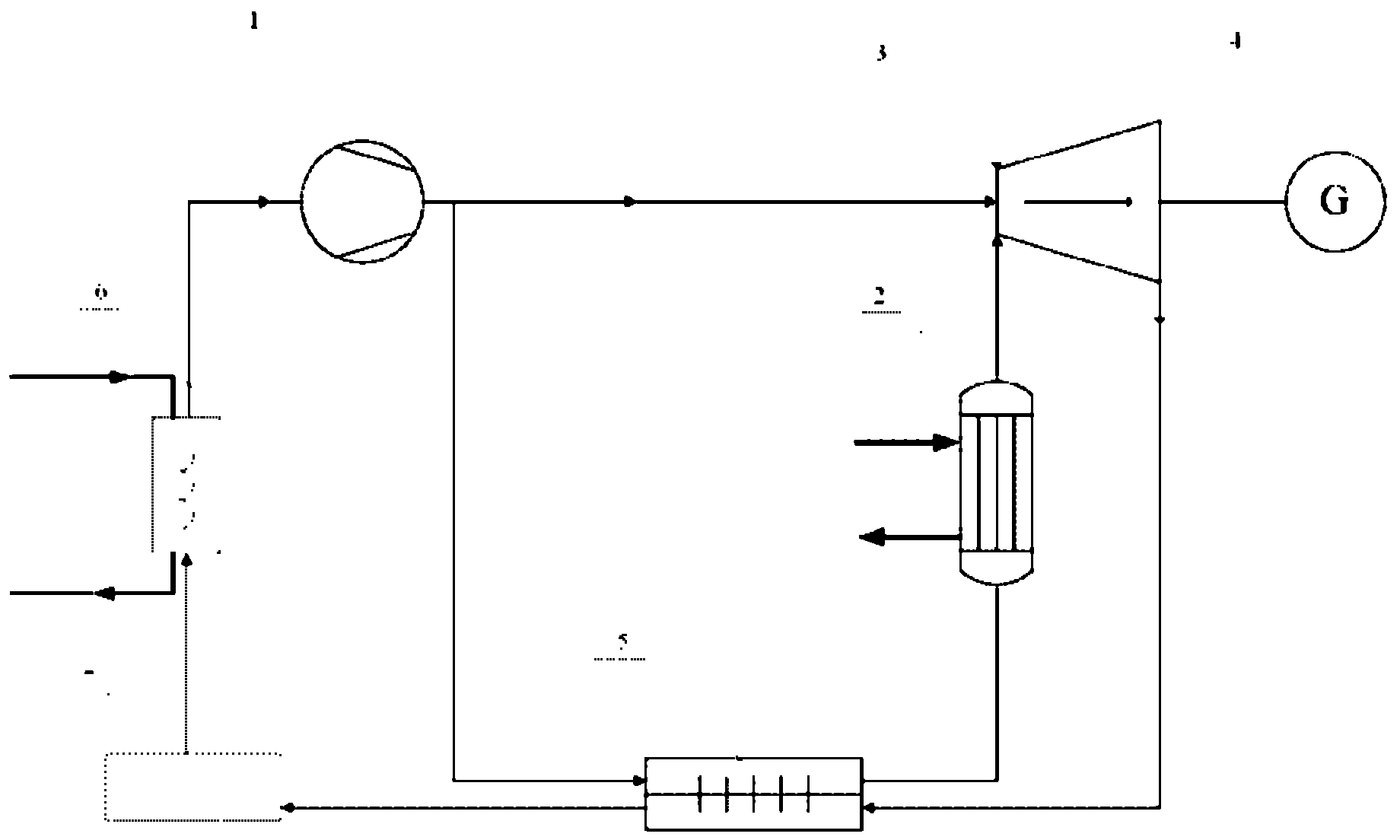
[0022] Such as figure 1 As shown, the embodiment of the present invention provides a power generation system based on supercritical carbon dioxide, including a compressor 1, a heat collector 2, a carbon dioxide turbine 3, a generator 4 and a cooling device, wherein the cooling device is a heat exchanger 6 and an absorption type cooler7. The outlet of the compressor 1 is divided into two paths, one path is directly connected with the inlet of the carbon dioxide turbine 3, and the other path is connected with the inlet of the heat collector 2 using an external heat source, and the outlet of the heat collector 2 is connected with the inlet of the carbon dioxide turbine 3, and the carbon dioxide The output of the turbine 3 is connected to the input of a generator 4 . Since the power generation system uses carbon dioxide as a f...


PUM


Abstract

The invention relates to the technical field of power generating systems and methods, in particular to a power generating system based on supercritical carbon dioxide, which comprises a compressor, a heat collector, a carbon dioxide turbine, a generator and a cooling device. An outlet of the compressor is connected with an inlet of the heat collector, an outlet of the heat collector is connected with an inlet of the carbon dioxide turbine, an output end of the carbon dioxide turbine is connected with an input end of the generator, an outlet of the carbon dioxide turbine is connected with an inlet of the cooling device, an outlet of the cooling device is connected with an inlet of the compressor, and accordingly a loop is formed. Heat is absorbed from the outside by the supercritical carbon dioxide in the closed loop to carry out heat circulation, and accordingly the power generating system not only can be used for generating power, but also can provide air conditioning refrigeration and hot water for users. Compared with a traditional power generation mode by the aid of steam, the power generating system has the advantages that power generation efficiency is higher than that of the traditional power generation mode by the aid of steam by 10% to 20%, the system is exquisite and is compact in structure and free of environmental pollution, and equipment cost is low.

Description

technical field [0001] The invention relates to the technical field of power generation systems and methods, in particular to a power generation system based on supercritical carbon dioxide. Background technique [0002] At present, energy problems plague countries all over the world, and it is imminent to find efficient and environmentally friendly power generation methods. There are roughly several types of power generation in the world: hydropower, thermal power, tidal power, atomic power, wind power and solar power. Solar power generation is relatively economical, but due to the huge collection device and the difficulty of manufacturing technology, it cannot be formed on a large scale to provide people's daily needs. Nuclear power generation is also relatively economical, but cannot be adopted quickly due to dreaded safety concerns. Thermal power generation occupies the first place in the world's power generation, because it is a device that uses chemical energy to con...

Claims


Application Information

Patent Timeline
Patent Type & Authority Applications(China)
IPC IPC(8): F01K25/10
Inventor 王磊景玉鹏
Owner INST OF MICROELECTRONICS CHINESE ACAD OF SCI
Why Eureka
Try Eureka