Steel rail or bridge displacement monitoring device for fiber Bragg grating transformation ring

A fiber grating and displacement monitoring technology, which is applied in the field of rail displacement, rail or bridge displacement monitoring devices, can solve the problems of inability to realize automatic measurement, unstable sensor characteristics, and decreased sensor sensitivity, so as to achieve long-term maintenance of measurement accuracy and solve stability Problems, Effects of Simple Structure

Inactive Publication Date: 2012-07-25
WUHAN UNIV OF TECH
View PDF6 Cites 22 Cited by
  • Summary
  • Abstract
  • Description
  • Claims
  • Application Information

AI Technical Summary

Problems solved by technology

Laser displacement monitoring requires manual operation, limited measurement accuracy, and cannot realize automatic measurement, etc.; capacitive displacement sensors are affected by temperature due to the different materials that make up the sensor, causing measurement errors, and edge effects will also reduce sensor sensitivity and increase nonlinearity. Moreover, the interference of foreign objects or people on the trackside produces parasitic capacitance, which leads to unstable sensor characteristics; the video imaging technology needs to wipe the camera and scale due to environmental pollution, and bad weather is easy to damage the equipment

Method used


Image

  • Steel rail or bridge displacement monitoring device for fiber Bragg grating transformation ring
  • Steel rail or bridge displacement monitoring device for fiber Bragg grating transformation ring
  • Steel rail or bridge displacement monitoring device for fiber Bragg grating transformation ring

Examples


Embodiment Construction

[0031] The structure and installation method of the rail displacement monitoring device of the optical fiber grating deformation ring of the present invention will be further described below in conjunction with the accompanying drawings.

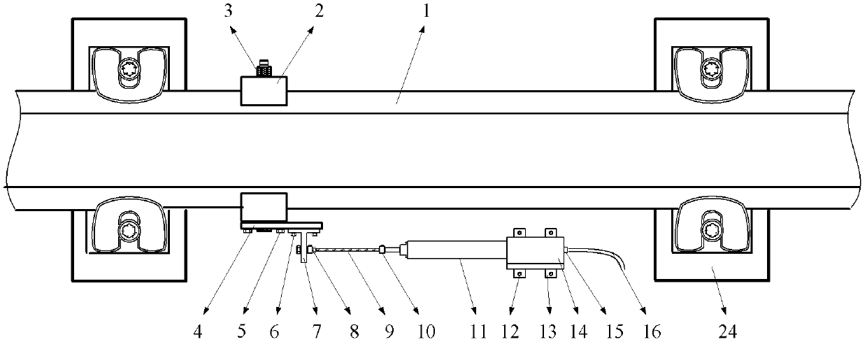
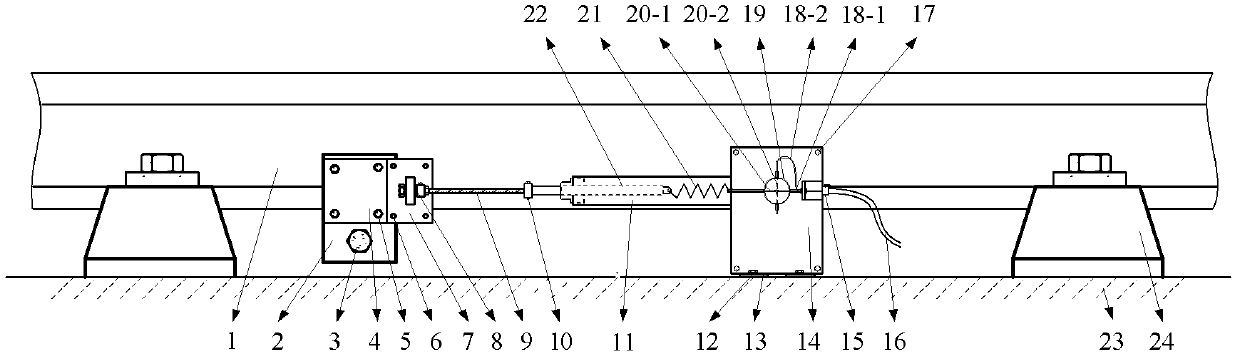
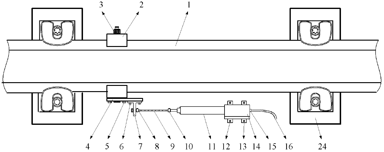
[0032] Such as figure 1 , 2 As shown, the monitoring device is composed of a fixing clip assembly, a connecting assembly, a fiber grating annular displacement sensing assembly, a pull rod assembly and a sensor housing device. When monitoring rail displacement, the whole device is installed between two sleepers 24 .

[0033]The fixing clip assembly is fixed on both sides of the bottom of the rail 1 by the rail fixing clip 2 and the fixing clip fastening bolt 3, and it is required to be fastened without looseness to ensure the accuracy of displacement measurement. Steel plate 4 is fixed on steel rail clamp 2 outsides (i.e. rail outside) with steel plate fastening bolt 5 again, and the steel cable fixed frame 7 is fixed on steel plate 4 exter...


PUM


Abstract

The invention provides a steel rail or bridge displacement monitoring device for a fiber Bragg grating transformation ring. The steel rail or bridge displacement monitoring device consists of a fixing clamp assembly, a connection assembly, a fiber Bragg grating transformation ring assembly, a pull rod assembly and a sensor shell device. One part of the steel rail or bridge displacement monitoring device is fixedly arranged on a steel rail or a beam body to be measured of the bridge, and the other part of the steel rail or bridge displacement monitoring device is fixedly arranged on a ballastless rail bed or a bridge reference beam body. The two parts of the steel rail or bridge displacement monitoring device are connected through the connection assembly. Two fiber Bragg gratings with different wavelengths are vertically cured on a rigid round ring. Force generated by that a target to be measured is displaced is transmitted to the rigid round ring through a pull ring and a spring, so that the two fiber Bragg gratings are inversely stressed. A center wavelength is offset to an inverse direction, so as to obtain the displacement of the target to be measured by overlapping the wavelength offset values. Therefore, the optical signal aberration generated by directly sticking the gratings is avoided and the interference caused by an environment temperature is omitted. The steel rail or bridge displacement monitoring device is applicable to long-term online monitoring, and is sensitive, stable, reliable, compact in structure and convenient to repair and maintain.

Description

technical field [0001] The invention relates to the technical field of rail displacement monitoring on a railway ballastless track bed, or the telescopic displacement monitoring of simply supported beams or continuous beams of railway bridges, and the technical field of optical fiber grating sensing. Specifically, it is a steel rail or bridge displacement monitoring device for a fiber grating deformation ring. Background technique [0002] Railway transportation plays a pivotal role in the national economy, and rails and bridges are the infrastructure of railway transportation. In recent years, with a large number of heavy-duty and speed-up trains running, as well as the construction and opening of multiple high-speed railway passenger lines, the monitoring requirements for their infrastructure have become higher and higher, and key technical means have been developed to monitor their operating status. It is extremely important to monitor the parameters to ensure its safe o...

Claims


Application Information

Patent Timeline
Patent Type & Authority Applications(China)
IPC IPC(8): G01B11/02
Inventor 李维来代鑫潘建军王俊杰程健刘芳
Owner WUHAN UNIV OF TECH
Why Eureka
Try Eureka