
Sealed canister for vacuum-desorbing physically-adsorbed hydrocarbon in soil

A technology of physical adsorption and sealed tanks, which is applied in the field of oil and gas exploration, can solve problems such as increasing analysis errors, occupying too much space, and complicated equipment operation, and achieves the effects of improving efficiency, broad application prospects, and simple operation

Active Publication Date: 2012-07-25
CHINA PETROLEUM & CHEM CORP +1
View PDF9 Cites 5 Cited by
  • Summary
  • Abstract
  • Description
  • Claims
  • Application Information

AI Technical Summary

Problems solved by technology

[0010] 1. The patent No. CN1308678C discloses a low-temperature desorption device and method for soil adsorbed hydrocarbons. Its disadvantages are: (1) high temperature and negative pressure act at the same time, and the degassing effect is good, but at the same time, water vapor will be mixed into the gas. Increased analysis error; (2) repeated operation of the sample will lead to gas leakage, resulting in human error; (3) complex operation of the equipment, suitable for analysis experiments of a small number of samples under laboratory conditions
[0015] 6. The patent No. US2010 / 0078435A1 discloses Seal jar1. The core technology is to divide a tank into multiple closed spaces, and different items can be placed separately, which solves the problem of using multiple tanks to occupy too much space
[0016] In short, there are many problems in the prior art. They are either low in desorption or complicated in operation, and are only suitable for degassing experiments of a small amount of samples under laboratory conditions.

Method used

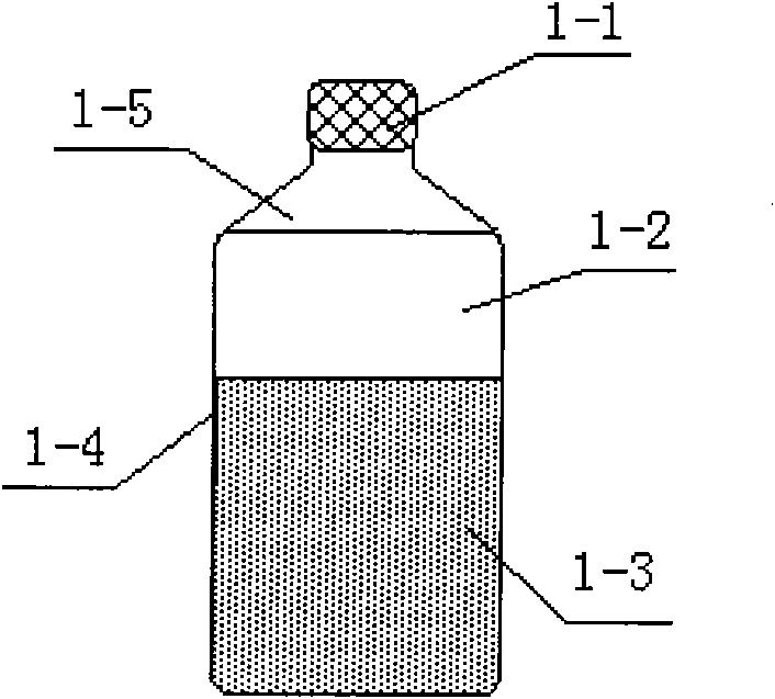
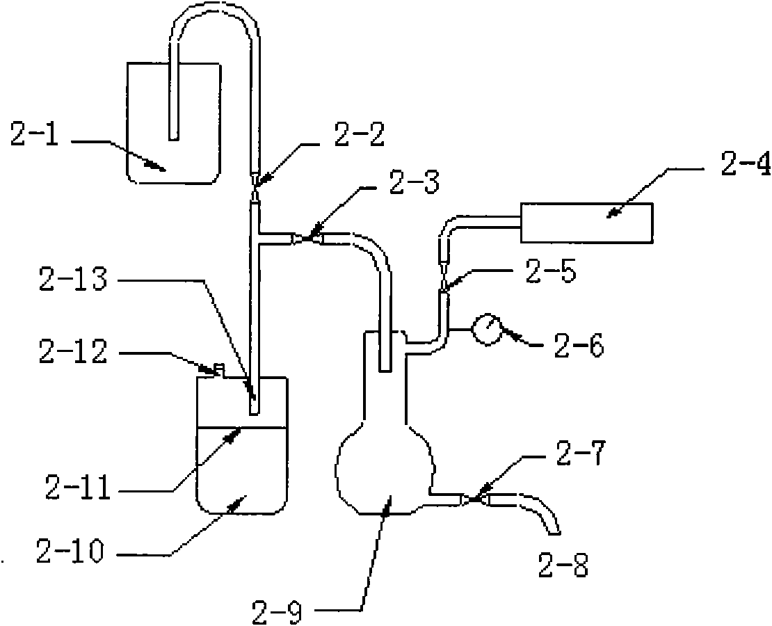

Image

  • Sealed canister for vacuum-desorbing physically-adsorbed hydrocarbon in soil
  • Sealed canister for vacuum-desorbing physically-adsorbed hydrocarbon in soil
  • Sealed canister for vacuum-desorbing physically-adsorbed hydrocarbon in soil

Examples


Embodiment Construction

[0054] Below in conjunction with accompanying drawing, the present invention is described in further detail:

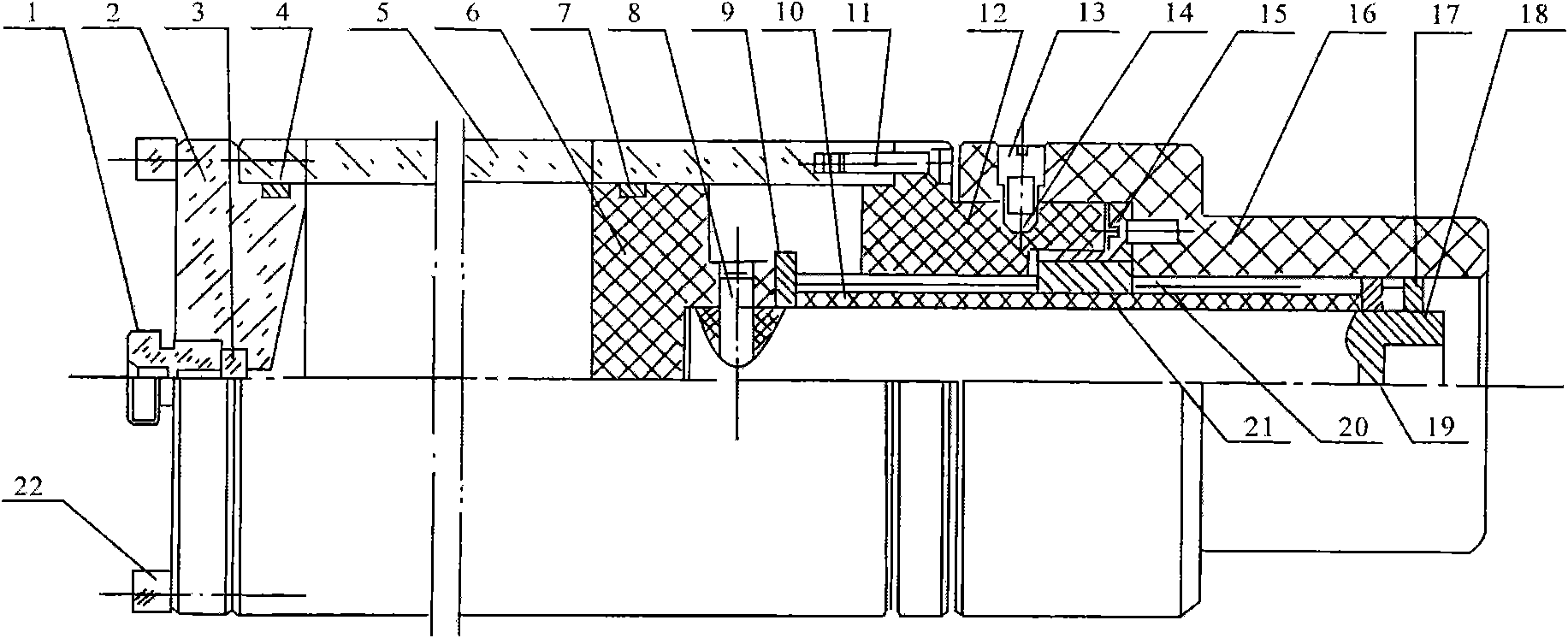
[0055] A kind of soil physical adsorption hydrocarbon vacuum desorption sealed tank, such as image 3 As shown, the sealed tank includes a cylinder body 5, an end cover 2 and a piston moving degassing assembly;

[0056] Wherein, the cylinder body 5 is a sleeve structure with openings at both ends, one end of which is a sampling end for putting in samples, and the other end is a working end for fixing the moving degassing assembly of the piston;

[0057] The end cap 2 is detachably installed on the sampling end of the cylinder 5 to seal the inner cavity of the cylinder 5; when loading the sample, open the end cap 2, put the sample in the cylinder 5 and cover the end cap 2 .

[0058] The piston moving degassing assembly includes an end cap nut 12, a piston 6 and a rotating sleeve 16; the piston moving degassing assembly is used to change the volume of the sealed tank ...


PUM


Abstract

The invention provides a sealed canister for vacuum-desorbing physically-adsorbed hydrocarbon in soil, belonging to oil / gas exploration field in petroleum geology. The canister includes a canister body, an end cover, and a piston mobile degassing assembly. The end cover is detachably fixed at one end of the canister body. The piston mobile degassing assembly is fixed at the other end of the canister body, and used for changing volume of the sealed canister to realize interior gas pressure rise / fall, thereby realizing the objective of desorbing physically-adsorbed gas in soil sample in the canister and pumping gas under positive pressure. The canister provided by the invention is used to extract physically-adsorbed hydrocarbon in soil sample in manner of total sealing, vacuum degassing by moving piston, and pumping under positive pressure; and has the advantages of high sealability and degassing degree, simple operation, convenient carriage, suitability for batch sample test, shortened sample analysis time and period, and improved efficiency. Meanwhile, cylinder of the canister is marked with volumetric scale, to realize direct and quantitative sampling in the field, avoid sample gas loss due to secondary operation, and guarantee consistent sample size.

Description

technical field [0001] The invention belongs to the field of oil and gas exploration in petroleum geology, and in particular relates to a vacuum desorption sealed tank for soil physical adsorption of hydrocarbons. Background technique [0002] The degassing technology of physical adsorption gas currently used in geochemical exploration is mainly to desorb and release the gas adsorbed on the surface of solid particles into the container through vacuuming and heating technology, usually in the laboratory, where the experimental samples are isolated in advance. Use a vacuum pump to pump out the gas in the experimental device, and then connect to the container containing the sample to create a negative pressure condition to desorb the adsorbed gas. [0003] Light hydrocarbons in oil and gas reservoirs can leak into the surface soil approximately vertically in a weak but detectable amount, which is the theoretical basis for oil and gas geochemical exploration. In the near-surfac...

Claims


Application Information

Patent Timeline
Patent Type & Authority Applications(China)
IPC IPC(8): G01N1/24
Inventor 王国建荣发准程同锦陈伟钧卢丽杨俊黄臣军李吉鹏
Owner CHINA PETROLEUM & CHEM CORP
Learn More