Method for imaging actual aperture foresight on basis of subspace projection

A technology of subspace projection and forward-looking imaging, which is applied in the field of imaging, can solve the problems of poor target resolution, inability to accurately detect the position of the target with angle measurement accuracy, and reduced signal-to-noise ratio, so as to facilitate system implementation, improve detection accuracy and imaging quality effect

Inactive Publication Date: 2012-07-25
XIDIAN UNIV
View PDF1 Cites 15 Cited by
  • Summary
  • Abstract
  • Description
  • Claims
  • Application Information

AI Technical Summary

Problems solved by technology

Although monopulse angle measurement has high measurement accuracy in theory, in practical applications, there are often the following limitations: when a complex-shaped target moves relative to the radar, it will cause the deviation between the apparent center of the target and the actual center of the target, Angular flicker phenomenon occurs, which restricts the imaging quality; the single-pulse forward-looking imaging technology cannot measure the angles of different scattering centers in the same range unit, and can only obtain the positions of equivalent scattering points, which reduces the accuracy of angle measurement; when the same beam memory When there are many targets, the angle measurement accuracy will drop sharply and even the position of the target cannot be detected accurately, especially when there are two or more targets with similar energy in the beam azimuth range within a certain distance unit, the angle measurement accuracy is especially Low; in monopulse forward-looking imaging, each angle-m

Method used


Image

  • Method for imaging actual aperture foresight on basis of subspace projection
  • Method for imaging actual aperture foresight on basis of subspace projection
  • Method for imaging actual aperture foresight on basis of subspace projection

Examples


Embodiment Construction

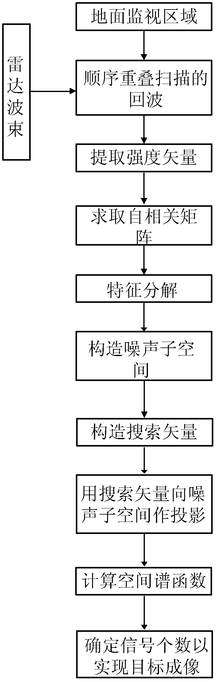
[0045] refer to figure 1 , the implementation steps of the present invention are as follows:

[0046] Step 1: Sequential overlapping scanning of the ground monitoring area is carried out by transmitting radar beams at equal intervals to obtain radar echo data Y;

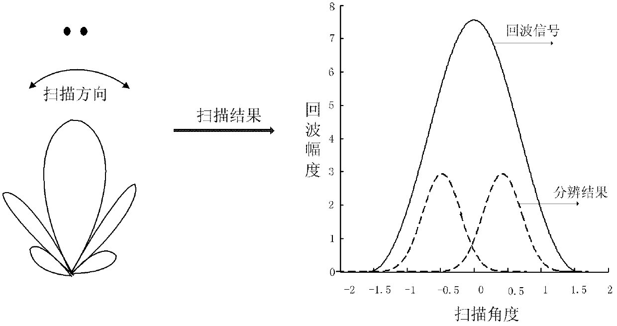
[0047] refer to figure 2 , in this step, the airborne radar sequentially overlaps and scans the ground surveillance area, that is, the radar echo data is regarded as the convolution of the antenna beam and the target information, and the echo data Y is obtained by emitting radar beams at equal intervals.

[0048] Step 2: Perform a modulo operation on the echo data Y to extract its intensity vector X:

[0049] X=|Y(k)|, 1)

[0050] Wherein, |·| represents a modulo operation, k=1, 2, . . . , K, K represents the length of the echo data.

[0051] Express the intensity vector X as a multiply-accumulate form of the signal amplitude value and the pattern vector:

[0052] X = Σ ...


PUM


Abstract

The invention discloses a method for imaging an actual aperture foresight on basis of subspace projection, which mainly solves the high resolution imaging problem of a right ahead object of a flightpath. The method has the detection processes that: 1) radar beams are sent out at equal intervals for carrying out sequence overlap scanning on a ground monitoring area to obtain the radar return data; 2) a modular arithmetic is utilized to extract the intensity vector of the return data; 3) the autocorrelation matrix of the intensity vector of the return data is gained; 4) eigen decomposition is carried out on the autocorrelation matrix; 5) the corresponding eigenvector of a small eigenvalue is used for forming a noise subspace; 6) a pattern search vector is defined; 7) the pattern search vector is projected into the noise subspace; 8) the peak values of a spatial spectrum function are calculated; and 9) the number of the signal is determined according to the number of the peak values of the spatial spectrum function for realizing foresight imaging. The method has the advantage of improving the resolution precision of an adjacent target in a main lobe, and can be used for an airborne radar monitoring system in the imaging field for realizing the detection and the recognition for a target on a track line.

Description

technical field [0001] The invention relates to the field of imaging, in particular to the problem of high-resolution imaging of a target directly in front of a flight track, which can be used in an airborne radar monitoring system to detect and identify targets along the direction of the flight track. Background technique [0002] In the ever-changing modern high-tech warfare environment in the future, battlefield information is complex and changeable, and fighters are fleeting. Timely and correct battlefield detection and tactical reconnaissance are related to the success or failure of the war. Therefore, it is necessary to require the radar imaging system to have a certain imaging accuracy and imaging range. However, when the antenna beam is close to coincident with the track line, since the ground targets distributed on both sides of the track have the same Doppler history, aliasing is likely to occur, and the Doppler change rate of the target is very small, the azimuth ...

Claims


Application Information

Patent Timeline
IPC IPC(8): G01S13/89G01S7/41
Inventor 杨志伟廖桂生杨凯新刘笑菲曾操何嘉懿夏桂琴
Owner XIDIAN UNIV
Why Eureka
Try Eureka