Automobile low-voltage power supply charging device
A low-voltage power supply and charging device technology, which is applied to battery circuit devices, circuit devices, electric vehicles, etc., can solve problems such as battery hazards, high-current charging of batteries, and inability to meet the requirements of large load currents of electrical appliances, so as to reduce damage, The effect of extending the service life
- Summary
- Abstract
- Description
- Claims
- Application Information
AI Technical Summary
Problems solved by technology
Method used
Image


Examples
Embodiment 1
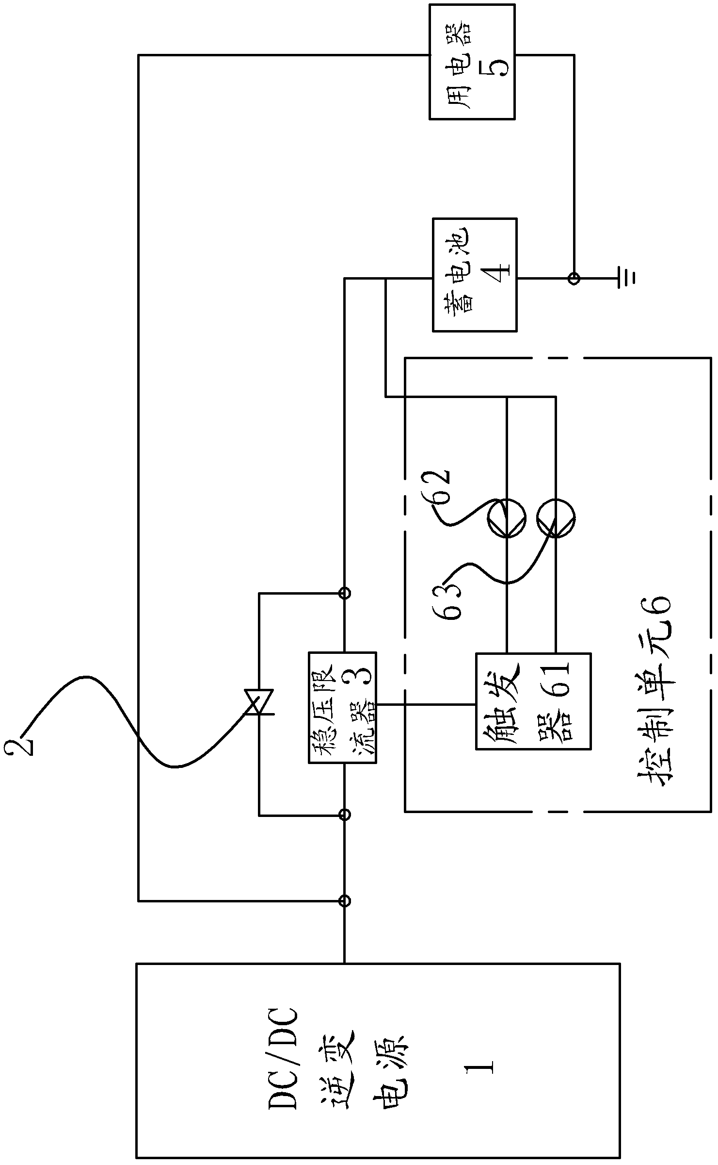
[0028] Embodiment one, such as figure 1 , 2 As shown, the automobile low-voltage power supply charging device includes an automobile DC / DC inverter power supply 1 and a storage battery 4, the output terminal of the automobile DC / DC inverter power supply 1 supplies power to the vehicle electrical appliance 5, and the output terminal of the automobile DC / DC inverter power supply 1 terminal also charges the battery 4 through the voltage regulator current limiter 3. The freewheeling diode 2 is connected in parallel at both ends of the voltage regulator current limiter 3 so that the battery 4 supplies power to the vehicle electrical appliance 5, the anode of the freewheeling diode 2 is connected to the positive pole of the battery 4, and the cathode of the freewheeling diode 2 is connected to the DC / DC inverter of the vehicle. Connect the variable power supply 1.
[0029] The voltage stabilizing current limiter 3 is connected with a control unit 6 capable of controlling the volta...
Embodiment 2
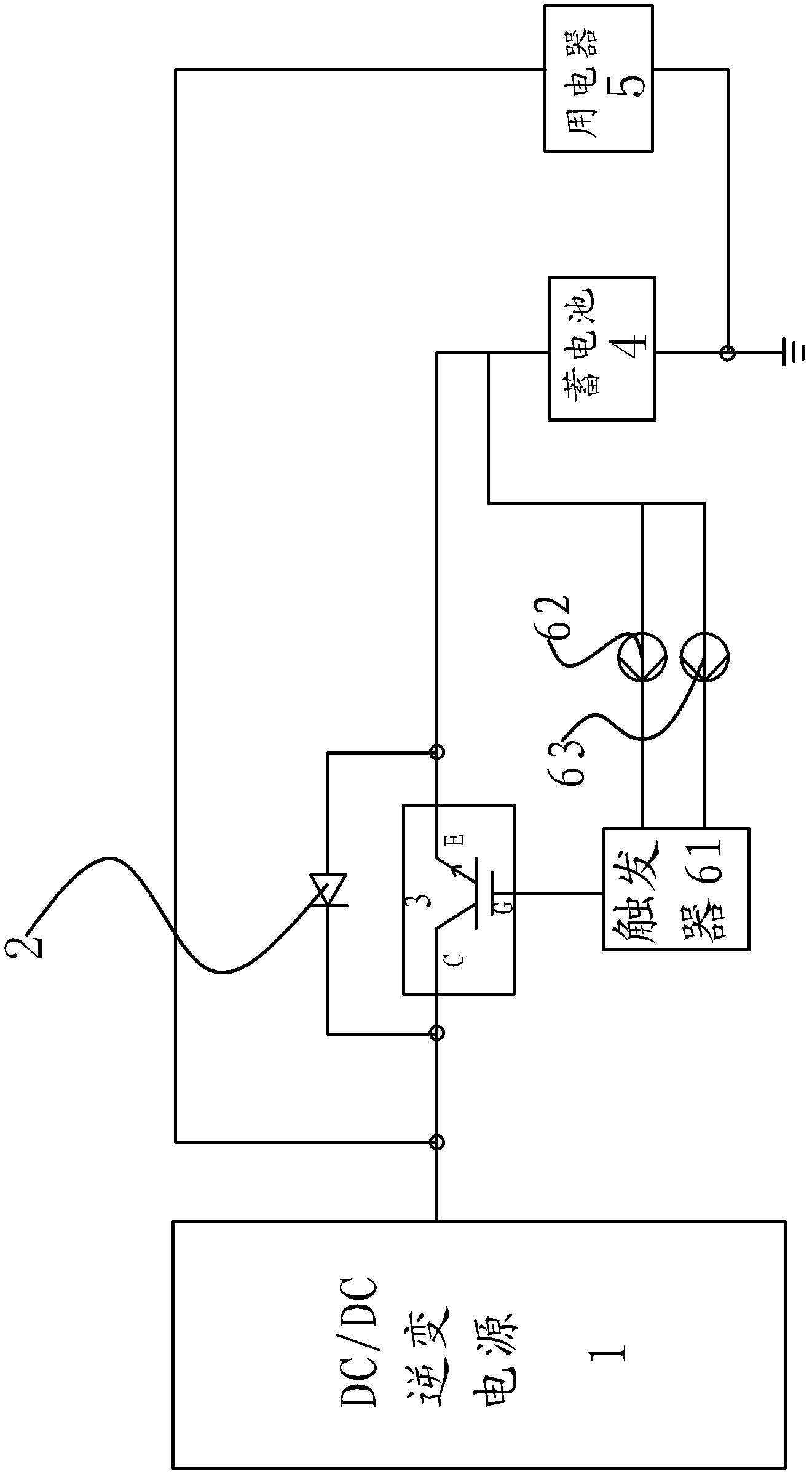
[0033] Embodiment two, such as figure 1 , image 3 As shown, as the second scheme of the voltage stabilizing current limiter 3, in the vehicle low-voltage power supply charging device, the voltage stabilizing current limiter 3 includes an IGBT, the input terminal of the trigger 61 is connected with the gate G of the IGBT, and the set of the IGBT The electrode C is connected to the output terminal of the automobile DC / DC inverter power supply 1 , and the emitter E of the IGBT is connected to the positive pole of the storage battery 4 . All the other connection structures are the same as in Embodiment 1. The trigger 61 controls the voltage applied to the gate G of the IGBT, thereby controlling the change of the turn-on and turn-off time of the collector C and the emitter E of the IGBT to control the output current, ensuring that the DC / DC inverter power supply can charge the battery The current is the most suitable small current for the battery.
Embodiment 3
[0034] Embodiment three, such as figure 1 , Figure 4 As shown, the triode in the above-mentioned stabilized current limiter 3 is replaced by a field effect tube. The present embodiment is an example of a MOS tube in a field effect tube. The source S of the MOS tube is connected to the DC / DC inverter power supply of the car through a wire 1 connection, the gate G of the MOS transistor is connected to the output terminal of the flip-flop 61, the drain D of the MOS transistor is connected to the storage battery 4, and the freewheeling diode 2 is reversely connected between the source S and the drain D of the MOS transistor , and the rest of the connection structure is the same as that of Embodiment 1. The trigger 61 uses the detection signals of the temperature sensor 62 and the current sensor 63 as a trigger signal to output a control current to change the current of the gate G of the MOS transistor, which also changes the voltage between the gate and the source, thereby chang...
PUM
 Abstract
Description
Claims
Application Information