Air flow pre-heater for water cooled wall of dilute nitric acid production process

A production process and water-cooled wall technology, applied in the field of dilute nitric acid production equipment, can solve problems such as difficult maintenance, reduced air volume, and increased evaporation load in the ammonium nitrate process, achieving the effects of increasing steam production, improving service life, and eliminating the risk of rupture

Inactive Publication Date: 2012-08-01
FUJIAN YONGAN SHUANGHUA CHEM
View PDF3 Cites 0 Cited by
  • Summary
  • Abstract
  • Description
  • Claims
  • Application Information

AI Technical Summary

Problems solved by technology

[0004] The temperature of the process gas entering the porous cover tube sheet can reach 700°C. Due to the large temperature difference, it is very easy to cause cracks in the tube sheet, resulting in primary air leakage into the process gas. On the one hand, the amount of air entering the oxidation furnace is reduced, and the production load is reduced. On the one hand, the concentration of nitrogen oxides in the process gas is reduced, resulting in a decrease in the concentration of finished acid, which increases the evaporation load of the ammonium nitrate process and increases steam consumption. In addition, the leakage of nitrogen oxide gas due to tube plate cracks also affects the surrounding environment , at the same time, the preheater is in the heat exchange equipment system of the oxidation system, and maintenance is extremely difficult

Method used


Image

  • Air flow pre-heater for water cooled wall of dilute nitric acid production process
  • Air flow pre-heater for water cooled wall of dilute nitric acid production process
  • Air flow pre-heater for water cooled wall of dilute nitric acid production process

Examples


Embodiment Construction

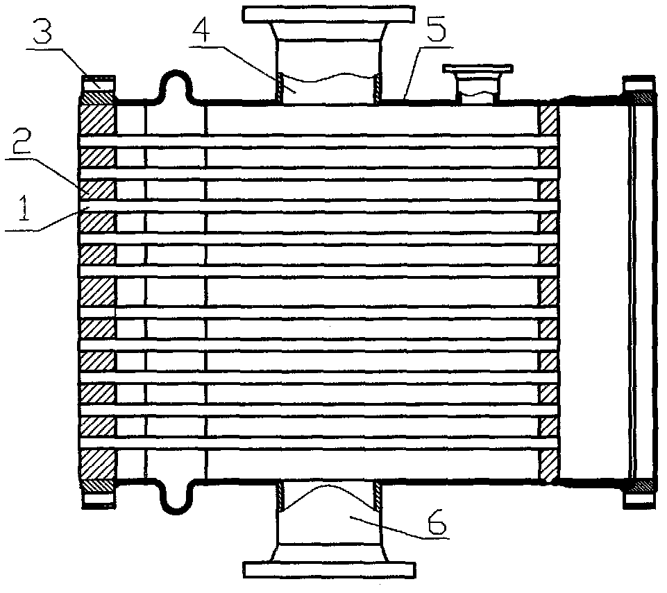
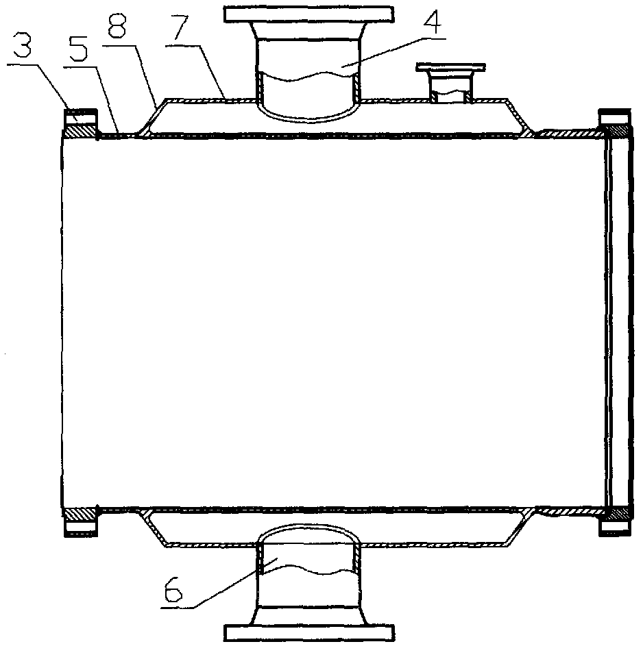
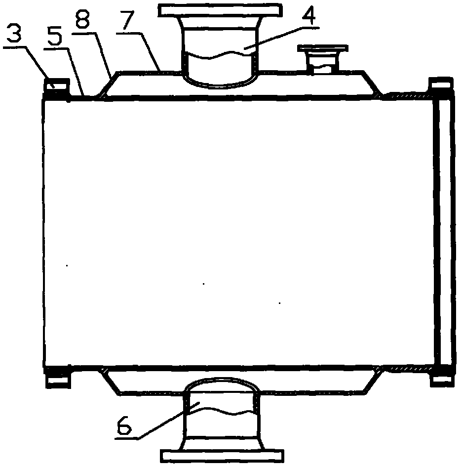
[0010] The invention includes a tubular body 5, a flange plate 3, a lower air intake pipe mouth 6, an upper exhaust pipe mouth 4, and a temperature measurement interface pipe respectively connected with the exhaust gas reheater output pipe and the waste heat boiler input pipe, and is characterized in that: tubular The inner cavity of the body 5 is a cavity; the two ends of the outer circle of the tubular body 5 are fixed with symmetrical tapered tubes 8, and the outer ports of the two tapered tubes 8 are fixedly connected with a round tube body 7 to form a ring-shaped water cooling chamber. The upper and lower through holes provided on the pipe wall of the body 7 are fixedly connected with the upper exhaust pipe port 4 and the lower air intake pipe port 6 respectively; the lower air intake pipe port 6 is connected with the bubble downcomer of the waste heat boiler, and the upper exhaust pipe port 4. It is connected with the bubble return pipe of the waste heat boiler; the tempe...


PUM


Abstract

The invention discloses an air flow pre-heater for a water cooled wall of a dilute nitric acid production process, and relates to dilute nitric acid production equipment. The air flow pre-heater comprises a tubular body, a flange, a lower air inlet pipe orifice, an upper exhaust pipe orifice and a temperature measuring port pipe, wherein the tubular body is communicated with a tail gas re-heater output pipe and a waste heat boiler input pipe respectively. The air flow pre-heater is characterized in that: the cavity of the tubular body is an empty cavity; symmetric conical pipes are fixed to the two ends of the external circle of the tubular body; the outer ports of the two conical pipes are fixedly connected with a circular pipe body to form an annular water cooling cavity; the pipe wall of the circular pipe body is provided with an upper through hole and a lower through hole which are fixedly connected with the upper exhaust pipe orifice and the lower air inlet pipe orifice respectively; the lower air inlet pipe orifice is connected with a bubble downcast pipe of a waste heat boiler; the upper exhaust pipe orifice is connected with a bubble reflow pipe of the waste heat boiler; and the temperature measuring port pipe is fixedly connected with a temperature measuring through hole formed on the pipe wall of the circular pipe body. The air flow pre-heater has the advantages of not entering air preheating, eliminating rupture risk of a pipe plate, introducing bubble downcast water of the waste heat boiler for heat exchange, prolonging the service life of equipment and increasing steam yield.

Description

Technical field: [0001] The invention relates to dilute nitric acid production equipment, in particular to a gas flow preheater for the water wall of the dilute nitric acid production process. Background technique: [0002] At present, the production system of dilute nitric acid by high-pressure method is set such that gas ammonia flows through gas ammonia filter, gas ammonia heater, ammonia air mixer, oxidation furnace, tail gas reheater, air flow preheater, waste heat boiler, and multi-stage heat exchange equipment in sequence. , and then enter the absorption tower, where the process gas reacts with water to generate nitric acid. At the same time, the reaction air formed after the air is compressed, filtered, and water-cooled is divided into two paths through the tee and the regulating valve, one path directly enters the ammonia-air mixer, and the other path passes through the air flow preheater for heat exchange, and then enters the ammonia-air mixer and After filtering ...

Claims


Application Information

Patent Timeline
IPC IPC(8): C01B21/38
CPCY02P20/129
Inventor 陈能军黄业英徐德安李维德
Owner FUJIAN YONGAN SHUANGHUA CHEM
Why Eureka
Try Eureka