Test stand for self-adaptive power recovering of hydraulic pump

An adaptive, hydraulic pump technology, applied in the field of test benches, can solve problems such as unavoidable overflow loss, throttling loss, complex and large test equipment, etc., to achieve excellent power recovery effect, small throttling pressure difference loss, The effect of optimal power recovery effect

Inactive Publication Date: 2012-08-01
XUZHOU MINGSHUO MACHINERY TECH
View PDF2 Cites 18 Cited by
  • Summary
  • Abstract
  • Description
  • Claims
  • Application Information

AI Technical Summary

Problems solved by technology

The early hydraulic pump test benches were fully loaded by the overflow and throttling method, and the energy output by the motor was almost completely converted into heat energy. On the one hand, this made the test consume a lot of energy. device, which consumes additional power
Especially for high-pressure and high-flow tests on hydraulic pumps, the energy consumption is even greater, and it may even have an impact on the relevant power grid.
For this reason, the following energy-saving test methods using power recovery methods have been proposed: (1) Electric power recovery method, which directly connects the outlet of the pump under test with the inlet of the loading motor, and the loading motor drives the generator to generate electric energy, which is passed through the inverter. Transform the feedback grid to achieve power recovery; since the feedback grid requires a set of devices to ensure that the regenerative power and the grid have the same phase, the implementation is technically complex, expensive, and the effect is not ideal. In order to prevent the load generator from reversing, it is necessary to increase safety control system, resulting in complex and large test equipment
(2) Mechanical compensation power recovery method, the tested pump is coaxially connected with the motor and the loading motor, the pressure oil output by the tested pump drives the loading motor to rotate, and the loading motor drives the tested pump through mechanical transmission. The motor, the tested pump, the loading motor, and the tested pump reciprocate to achieve the purpose of power recovery; but it has the following shortcomings: First, because the loading motor and the electric motor drive the tested pump at the same time, there will be "parasitic" power loss; The second is the existence of unavoidable overflow loss, and the size of the overflow loss depends to a large extent on the flow matching between the tested pump and the loading motor. If the matching is not proper, the power recovery effect is not ideal; the third is through the following methods Loading is carried out, that is, the output flow of the pump under test is more than the flow required by the loading motor, and the excess oil will cause "oil trapping" in the cavity formed by the connecting pipe between the two, and will flow from the active gap between the pump under test and the loading motor. Leaks out, so the test pressure for this loading method is susceptible to a variety of non-linear factors
(3) Hydraulic compensation power recovery method, the tested pump is mechanically connected with the loading motor coaxially, the outlet of the tested pump is connected with the loading motor inlet through a throttle valve for loading, and the compensation pump is connected in series or parallel in the hydraulic oil circuit In this method, a certain pressure oil is provided to compensate the insufficient energy of the system with hydraulic energy; when this method is used for hydraulic pump tests, some parameters cannot be changed, and only part of the test can be done, so it is mostly used for high-speed hydraulic motors, low-speed high-torque motors It is not suitable for hydraulic pumps; moreover, because it is necessary to adjust the size of the orifice to adjust the load and pressure, there is a throttling loss, which affects the power recovery effect

Method used


Image

  • Test stand for self-adaptive power recovering of hydraulic pump
  • Test stand for self-adaptive power recovering of hydraulic pump
  • Test stand for self-adaptive power recovering of hydraulic pump

Examples


Embodiment 1

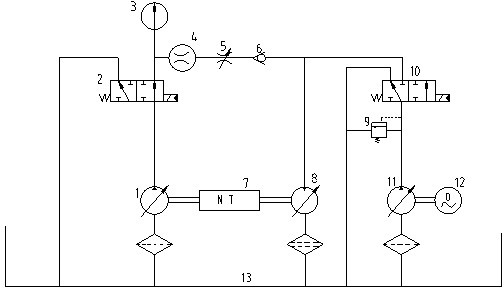
[0013] Embodiment one, as figure 1 As shown, the hydraulic pump adaptive power recovery test bench is mainly composed of the tested pump circuit, the loading motor circuit, the compensation pump circuit, and the detection element. The tested pump circuit includes the tested pump 1, the left reversing valve 2 and the connecting oil pipe. The tested pump is a quantitative pump or a one-way variable pump. The oil pipe is connected with the pressure oil port of the left reversing valve 2; the left reversing valve 2 is a two-position three-way reversing valve, and its two working oil ports are respectively connected with the oil tank 13 and the oil inlet of the loading motor 8;

[0014] The loading motor circuit includes a loading motor 8, a throttle valve 5, and a one-way valve 6. The loading motor 8 is a variable motor, and the loading motor 8 is coaxially connected with the tested pump 1; the maximum theoretical displacement of the loading motor 8 is q Mmax The theoretical dis...

Embodiment 2

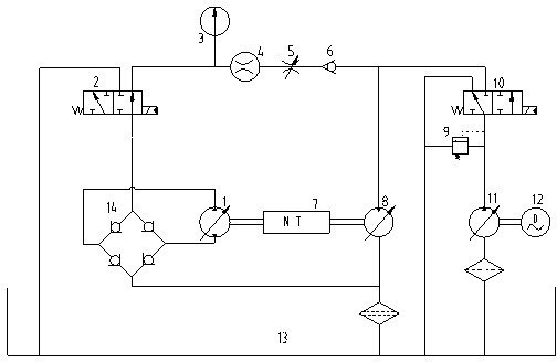
[0021] Embodiment two, figure 2 As shown, it is basically the same as the embodiment, and the similarity is omitted. The difference: the test bench with two-way variable pump, in figure 1 A rectifying valve group 14 composed of 4 check valves is added on the basis of the above, and the oil outlets of the tested pump 1, the left reversing valve 2 and the loading motor 8 are connected to each other through the rectifying valve group 14.

[0022] Working principle and working process:

[0023] First, adjust the displacement of the loading motor 8 to the maximum value, adjust the displacement of the compensation pump 11 to a smaller value, and respectively place the left reversing valve 2 and the right reversing valve 10 in the left position, so that the tested Both the oil outlets of the pump 1 and the compensation pump 11 are directly connected with the oil tank 13, and at the same time, the opening of the throttle valve 5 is opened to the maximum.

[0024]Next, start the mo...


PUM


Abstract

A test stand for self-adaptive power recovering of a hydraulic pump mainly comprises a tested pump loop, a loading motor loop, a compensating pump loop and a detecting element. The tested pump loop comprises a tested pump and a left reversing valve. The loading motor loop comprises a loading motor, a throttle valve and a one-way valve, and the throttle valve and the one-way valve are connected in series to the pipe between the left reversing valve and the loading motor. The compensating pump loop comprises a compensating pump, a safety valve and a right reversing valve, wherein the compensating pump is coaxially connected with an electromotor mechanically; an oil outlet of the compensating pump is communicated to an oil inlet of the safety valve and an oil inlet of the right reversing valve respectively; an oil return port of the safety valve is communicated with an oil tank; the right reversing valve is a two-position three-way reversing valve, and two working oil ports are respectively communicated with oil inlets of the oil tank and the loading motor. The detecting element comprises a pressure gauge, a high-pressure flow gauge and a torque speed sensor. The test stand for self-adaptive power recovering of the hydraulic pump, with applicability to tests of various hydraulic pumps, has the advantages of simple structure, great power recovering effect and high operational reliability.

Description

technical field [0001] The invention relates to a test bench, in particular to an adaptive power recovery test bench suitable for performance detection and reliability assessment of various hydraulic pumps. Background technique [0002] The hydraulic pump test bench is a necessary means for performance testing, reliability assessment and related law research of hydraulic pumps. The early hydraulic pump test benches were fully loaded by the overflow and throttling method, and the energy output by the motor was almost completely converted into heat energy. On the one hand, this made the test consume a lot of energy. The device consumes additional power. Especially when performing high pressure and large flow tests on hydraulic pumps, the energy consumption is even greater, and it may even have an impact on the relevant power grid. For this reason, the following energy-saving test methods using power recovery methods have been proposed: (1) Electric power recovery method, whi...

Claims


Application Information

Patent Timeline
Patent Type & Authority Applications(China)
IPC IPC(8): F15B19/00F15B21/14
Inventor 陈国安范天锦曹斌祥
Owner XUZHOU MINGSHUO MACHINERY TECH
Why Eureka
Try Eureka