Novel flue gas waste heat recycling device

A flue gas waste heat and recovery device technology, which is applied to heat exchanger types, indirect heat exchangers, lighting and heating equipment, etc., can solve the problems that waste heat utilization equipment cannot generate hot air and hot water at the same time, and the heat exchange efficiency is low , to achieve the effects of reducing production costs, less steel consumption, and reducing floor space

Active Publication Date: 2012-08-01
代树明
View PDF7 Cites 8 Cited by
  • Summary
  • Abstract
  • Description
  • Claims
  • Application Information

AI Technical Summary

Problems solved by technology

[0003] The purpose of the present invention is to solve the technical problem that the waste heat utilization equipment in the prior art cannot produce hot air and hot water at the same time, and the heat exchange efficiency is low

Method used


Image

  • Novel flue gas waste heat recycling device

Examples


Embodiment Construction

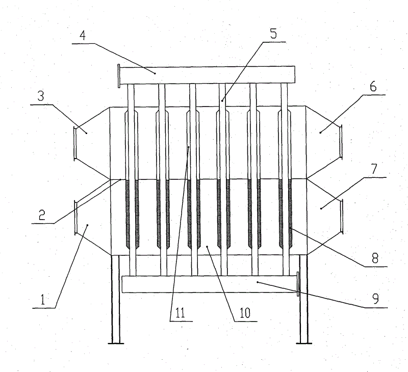
[0011] Referring to the accompanying drawings, the present invention includes 4 water inlet headers located on the upper part of the 10 shell side, connected to the 4 water inlet headers are the 5 heat exchange tube assemblies located inside the 10 shell side, and 11 closed chambers outside the 5 heat exchange tube assemblies The body contains half of the 8 superconducting liquid, and the other half is a vacuum. The lower part of the 5 heat exchange tube assembly is connected to the 9 water outlet header, and the 10 shell side is connected to the 1 smoke inlet, 7 smoke outlet, 3 hot air outlet and 6 Cold air inlet, 2 partitions divide 10 shells into flue gas channel and air channel.

[0012] The working principle of the present invention: high-temperature flue gas enters the interior of shell side 10 from smoke inlet 1, and quickly scours 5 heat exchange tube assemblies, 5 heat exchange tube assemblies 11 contain half of 8 superconducting liquid in the external airtight cavity,...


PUM


Abstract

The invention discloses a novel flue gas waste heat recycling device, which comprises a flue inlet, a flue outlet, a cold air inlet, a hot air outlet, a shell pass, a partition, a water inlet header, a water outlet header and heat exchange tube components. The water inlet header and the water outlet header are located at the top and bottom of the shell pass respectively, and are connected by the heat exchange tube components which are located in the shell pass. The outside of the shell pass is connected with the flue inlet, the flue outlet, the hot air outlet and the cold air inlet. The shell pass is divided into a flue gas passage and an air passage by the partition, so that the manufacturing of the outside shell of the traditional heater is omitted, the steel consumption is lowered, and the manufacturing cost is reduced. Airtight chambers are arranged outside the heat exchange tube components, and each of the airtight chambers is half full of superconductive liquid and half vacuum, so that the air and the water can absorb heat at the same time, the heat exchange effect is good, and the whole efficiency is improved. By the novel flue gas waste heat recycling device, cost of manufacturing, transportation, installation and management is reduced, and resources are saved greatly for the society.

Description

technical field [0001] The invention belongs to the technical field of energy-saving and environmental protection equipment, and relates to a novel flue gas waste heat recovery device. Background technique [0002] At present, various waste heat utilization devices such as air preheaters and water heaters are widely used in the flue gas tails of various furnaces, kilns and other industrial products, so as to recover the waste heat of the flue gas, reduce energy loss, and save energy. After the air preheater is installed at the gas tail, a water heater must be installed to completely recover the waste heat in the flue gas. In the prior art, the generation of hot air and hot water are completed by two independent devices. The air preheater is an energy-saving device for recovering the waste heat of the flue gas of the heating furnace. It has various structural forms: heat pipe type, smooth pipe type, finned tube type, reinforced tube type, and rotary type. These types have the...

Claims


Application Information

Patent Timeline
Patent Type & Authority Applications(China)
IPC IPC(8): F28D7/00F28D15/02
Inventor 代树明
Owner 代树明
Why Eureka
Try Eureka