Pilot protection method for power transmission line based on signal distance and Bergeron model

A transmission line, longitudinal protection technology, applied in the direction of the fault location, etc., can solve the problems of optical fiber current differential, incorrect action of protection, etc.

Inactive Publication Date: 2012-08-01
KUNMING UNIV OF SCI & TECH
View PDF4 Cites 14 Cited by
  • Summary
  • Abstract
  • Description
  • Claims
  • Application Information

AI Technical Summary

Problems solved by technology

However, traditional longitudinal protection, such as optical fiber current differential and high-frequency protection, is affected by the distributed capacitance of the ultra-high voltage long line, the difference in the transient characteristics and saturation of both sides of T A and the communication channel, and it is easy to cause incorrect action of the protection.

Method used


Image

  • Pilot protection method for power transmission line based on signal distance and Bergeron model
  • Pilot protection method for power transmission line based on signal distance and Bergeron model
  • Pilot protection method for power transmission line based on signal distance and Bergeron model

Examples


Embodiment 1

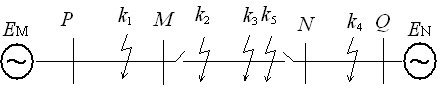
[0055] Embodiment 1: Simulation system such as figure 1 As shown, the transmission line M-N adopts the J.Marti frequency-dependent line model, and the total length of the line is 150km. Characteristic impedance in α mode Z c = 239.0203Ω, resistance r = 2.7188e-5Ω / m, wave velocity v = 2.9657e+8m / s. Phase A ground fault occurs in the line M-N, and the fault location is 10km away from the M terminal ( x =10km), such as figure 1 middle k 2 , Transition resistance 100 ohms.

[0056] When a fault occurs on the transmission line, the simulation sampling frequency is set to 20kHz, and within a short time window of 3 ms, the voltage at the M point at the head end and the N point at the end of the transmission line is measured u M 、u N and current i M 、i N , according to the expression of current distribution law along the Bergeron model, the measured voltage at the head end u M and current i M Simulation calculation of the current at the end of the transmission...

Embodiment 2

[0069] Embodiment 2: Simulation system such as figure 1 As shown, the transmission line M-N adopts the J.Marti frequency-dependent line model, and the line parameters are the same as those in Embodiment 1. Phase A ground fault occurs in the line M-N, and the fault location is 50km away from the M terminal ( x =50km), such as figure 1 middle k 3 , Transition resistance 300 ohms.

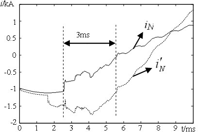
[0070] After the transmission line fails, follow the same method as in Example 1, take the simulation sampling frequency as 20kHz, and simulate and calculate the current at the end (N side) of the transmission line within a short time window of 3ms .

[0071] Take the tuning factor k a =0.6, set the setting value is 0.35. After calculation, the simulated current at the end of the transmission line and measured current i N Mutual distance =0.901, > , and it is judged as an intra-area fault of the transmission line.

Embodiment 3

[0072] Embodiment 3: simulation system such as figure 1 As shown, the transmission line M-N adopts the J.Marti frequency-dependent line model, and the line parameters are the same as those in Embodiment 1. Phase A ground fault occurs in the line P-M, and the fault location is 40km away from the M terminal ( x =40km), such as figure 1 middle k 1 , Transition resistance 100 ohms.

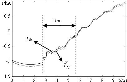
[0073] After the transmission line fails, the simulation sampling frequency is set to 20kHz, and within a short time window of 3 ms, the current at the end (N side) of the transmission line is simulated and calculated according to the same method as in Example 1 , to get the measured current at the terminal i N with analog current Waveform diagram such as image 3 shown.

[0074] Take the tuning factor k a =0.6, set the setting value is 0.35. After calculation, the simulated current at the end of the transmission line and measured current i N Mutual distance =0.0504, ≤ , ...


PUM


Abstract

The invention relates to a pilot protection method for a power transmission line based on signal distance and Bergeron model, belonging to the technical field of relay protection for electric power systems. The pilot protection method comprises the following steps of: when the power transmission line has faults, in a short-time window, measuring voltages (uM, uN) and currents (iM, iN) at the head end (M) point and the tail end (N) point of the power transmission line, simulating and calculating the current at the tail end of the power transmission line by using the actually measured voltage (uM) and current (iM) at the head end according to the line current distribution rule expression of the Bergeron model, comparing the waveforms of the quasi tail end current and the actually measured tail end current (iN), calculating the mutual distance degree between the quasi current and the actually measured current (iN), comparing the calculated mutual distance degree with the set mutual distance degree setting value, and identifying faults inside or outside the region according to the size relationship of the two mutual distance degrees. The pilot protection method is not influenced by excesssive resistance and fault initiating angle and has the advantages of quickly and reliably identifying faults inside and outside the region and the like.

Description

technical field [0001] The invention relates to a transmission line longitudinal protection method based on signal distance and Bergeron model, and belongs to the technical field of electric power system relay protection. Background technique [0002] In the traditional protection, the longitudinal protection can realize the quick action of the whole line, and has absolute selectivity, so it can meet the stability needs of the power system, and fully meet the selectivity, sensitivity, quick action and reliability requirements of the relay protection . However, traditional longitudinal protection, such as optical fiber current differential and high-frequency protection, is affected by the distributed capacitance of the ultra-high voltage long line, the difference in the transient characteristics and saturation of both sides of T A and the communication channel, and it is easy to cause incorrect action of the protection. [0003] In order to overcome the above shortcomings of...

Claims


Application Information

Patent Timeline
Patent Type & Authority Applications(China)
IPC IPC(8): G01R31/08
Inventor 束洪春蒋彪董俊田鑫萃
Owner KUNMING UNIV OF SCI & TECH
Why Eureka
Try Eureka