High-precision time interval measurement device
A time interval measurement, high-precision technology, applied in the direction of electrical unknown time interval measurement, time interval measurement devices, instruments, etc., can solve the problems of not making full use of clock phase information, not finding relevant information, and difficulty in high-precision measurement , to achieve the effect of facilitating function expansion, reducing risks, and stabilizing the system
- Summary
- Abstract
- Description
- Claims
- Application Information
AI Technical Summary
Problems solved by technology
Method used
Image
Examples
Embodiment 1
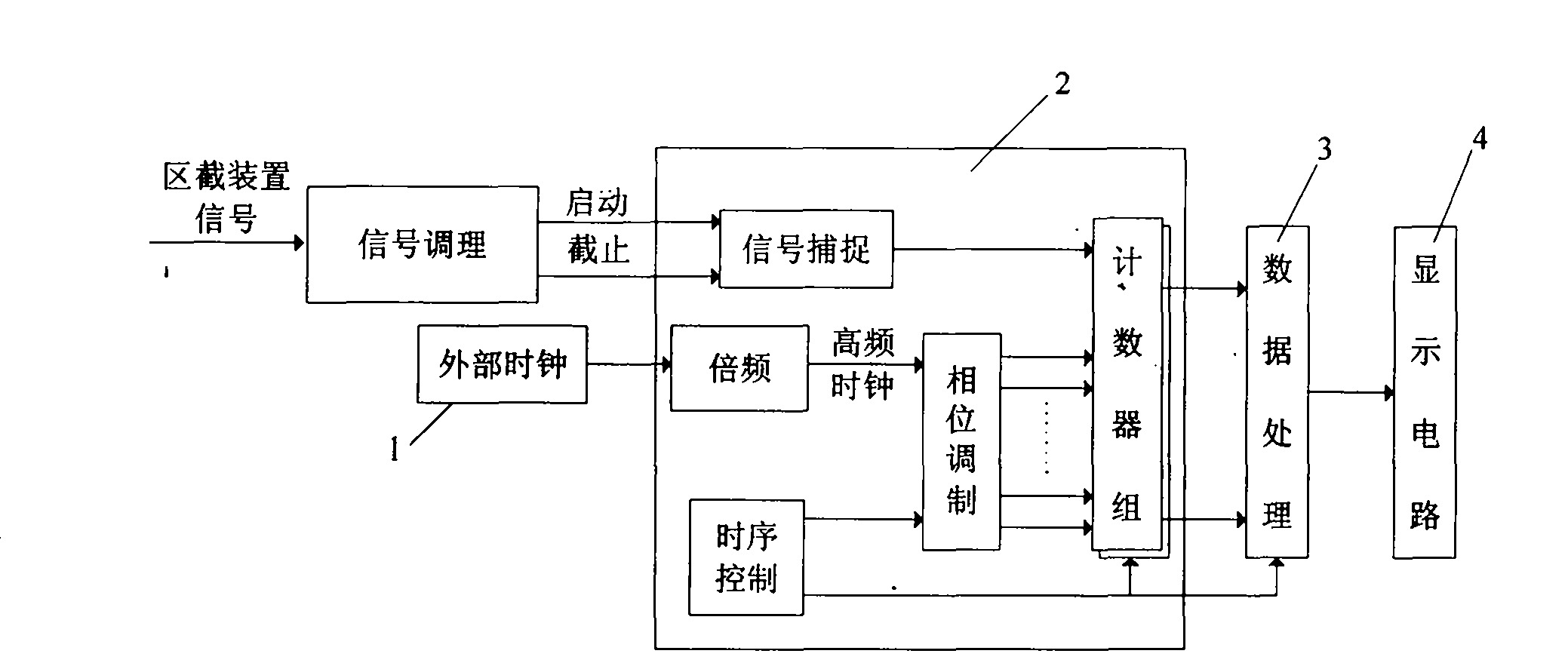
[0030] see figure 1, The measuring device includes: counting module, display circuit module, signal conditioning module, FPGA module, single-chip microcomputer module and high-precision crystal oscillator, the signal generated by the section device is connected to the signal conditioning module, and the output of the signal conditioning module is connected to the FPGA module, high-precision The clock signal of the crystal oscillator is connected to the dedicated clock input terminal of the FPGA module, and the output terminal of the FPGA module 2 is connected to the single-chip microcomputer module; the external high-precision crystal oscillator is frequency-multiplied and de-jittered under the action of the internal phase-locked loop of the FPGA module 2 to obtain a high-frequency clock , through phase-shift control inside the FPGA module 2, multiple clocks with N channels of the same frequency and fixed phase difference are generated. The asynchronous universal transceiver (...
Embodiment 2
[0037] The high-precision time interval measurement device is the same as that in Embodiment 1. The present invention is a high-precision time interval measurement device optimized and constructed on the basis of a high-precision time interval measurement method based on phase modulation. More devices can also be constructed. The degree of digitalization and integration continues to increase. The measuring device adopts digital processing chips such as other single-chip microcomputers, and the processing data is fast and efficient, and the present invention does not require manual participation in calculation. At the same time, the system is flexible in expansion and easy to integrate.
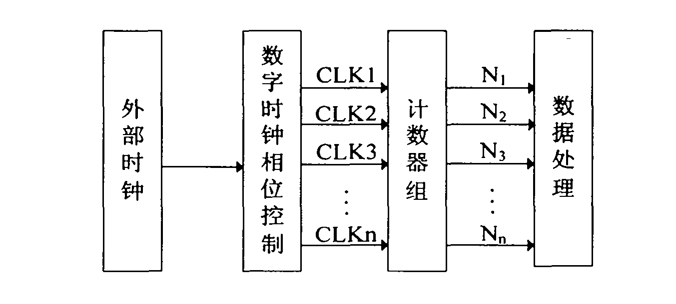
[0038] The high-precision time interval measurement method based on phase modulation is to convert an external high-precision clock into N multiple clock signals with the same frequency and fixed phase difference through clock digital phase shift control, and use this as the reference clock of...
Embodiment 3
[0058] The high-precision time interval measuring device is the same as Embodiment 1-2, and will be further described in detail below in conjunction with the accompanying drawings and in conjunction with the work of the present invention.
[0059] see figure 1The signal conditioning module of the present invention obtains the time interval signal T by filtering, amplifying, and shaping the signal generated by the sectioning device, that is to say, the processed time interval signal T is a standard signal that can be recognized by the FPGA module 2 . The external high-precision crystal oscillator 1 is frequency-multiplied and de-jittered under the action of the internal phase-locked loop of the FPGA module 2 to obtain a high-frequency clock, and then through phase-shift control to generate multiple clocks with the same frequency and fixed phase difference, which are driven separately The counters count pulses in their respective clock cycles. The count value obtained is transm...
PUM
 Abstract
Description
Claims
Application Information
 - R&D
- Intellectual Property
- Life Sciences
- Materials
- Tech Scout
- Unparalleled Data Quality
- Higher Quality Content
- 60% Fewer Hallucinations
Browse by: Latest US Patents, China's latest patents, Technical Efficacy Thesaurus, Application Domain, Technology Topic, Popular Technical Reports.
© 2025 PatSnap. All rights reserved.Legal|Privacy policy|Modern Slavery Act Transparency Statement|Sitemap|About US| Contact US: help@patsnap.com


