Compound control method of three-phase to two-phase orthogonal inverter power supply with reactive compensation function

A technology of inverter power supply and compound control, which is applied in reactive power compensation, reactive power adjustment/elimination/compensation, output power conversion devices, etc. problem, to achieve the effect of reducing reactive power compensation equipment and improving current waveform

Active Publication Date: 2012-08-01
HUNAN UNIV
View PDF2 Cites 9 Cited by
  • Summary
  • Abstract
  • Description
  • Claims
  • Application Information

AI Technical Summary

Problems solved by technology

[0003] The three-phase to two-phase orthogonal inverter power supply usually consists of two parts: a three-phase rectifier circuit (pre-stage) and a two-phase orthogonal inverter circuit (rear stage). The traditional two-phase orthogonal inverter power supply usually uses two The H-bridge single-phase inverter circuit is used as the main circuit, and a total of 8 large-capacity power switching devices are required, and the hardware cost is relatively high.
Since the voltage vector of the two-phase inverter circuit in the latter stage is asymmetrical, its space state vector constitutes a non-equilateral length hexagonal deformation, so it is very complicated to determine the switching time when using this method
Based on the PI control method in the rotating coordinate system, although the zero steady-state error control of the AC signal can be realized, the control process does not respond to the low-order harmonic components in the feedback signal, and the harmonic current generated in the power supply will affect the electromagnetic stirring. device function
In addition, in order to achieve a good stirring effect, the electromagnetic stirrer usually works in three working states: forward rotation, stop operation, and reverse rotation. The control method of the three-phase rectifier circuit is to pursue the unity power factor at the input side of the rectifier circuit, but there is no report on the control method of the front-stage rectifier circuit as a reactive power compensation device for reactive power compensation to the external power grid while rectifying.

Method used


Image

  • Compound control method of three-phase to two-phase orthogonal inverter power supply with reactive compensation function
  • Compound control method of three-phase to two-phase orthogonal inverter power supply with reactive compensation function
  • Compound control method of three-phase to two-phase orthogonal inverter power supply with reactive compensation function

Examples


Embodiment Construction

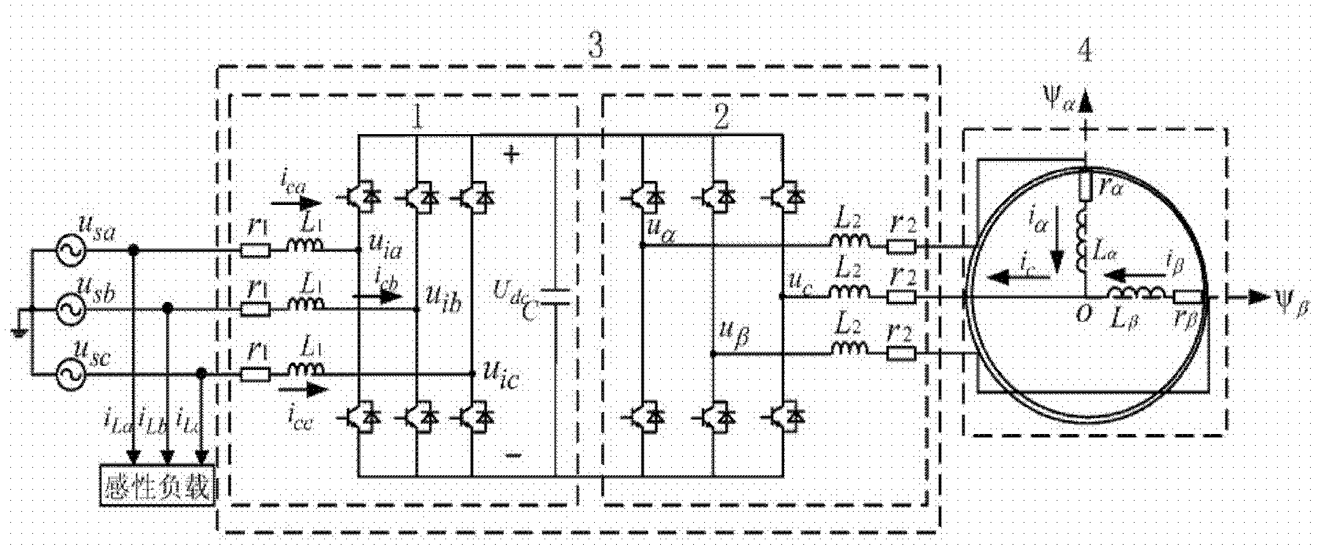
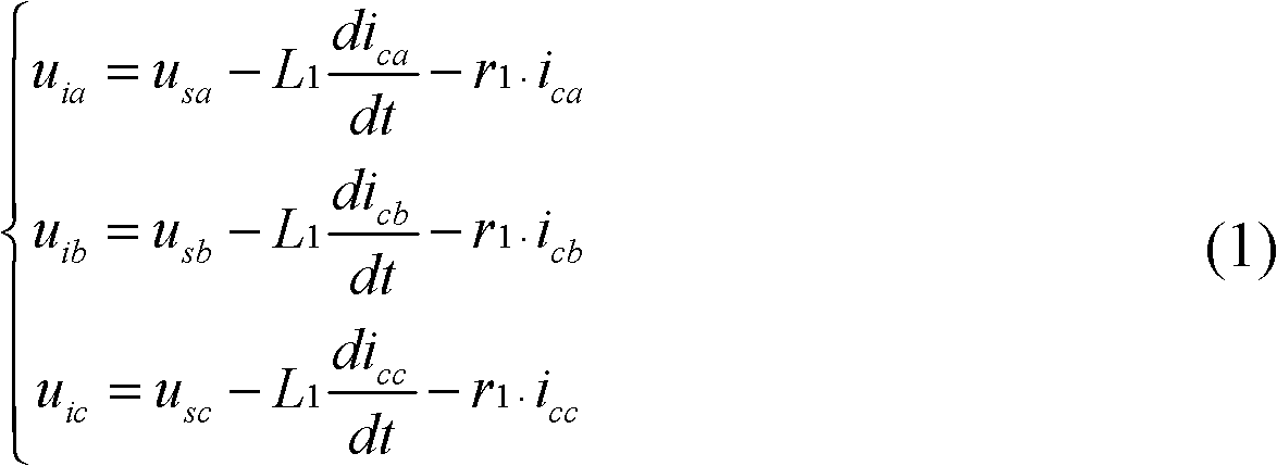
[0016] Such as figure 1 As shown, the main circuit of the three-phase to two-phase inverter power system adopted in an embodiment of the present invention includes a three-phase power supply, an input inductance L 1 , three-phase PWM rectifier bridge, three-leg inverter bridge, output inductor L 2 , electromagnetic stirrer, three-phase PWM rectifier bridge and three-arm inverter bridge are connected to form a three-phase two-phase orthogonal inverter power supply, and the switching devices in the three-phase PWM rectifier bridge and three-arm inverter circuit are IGBT or smart Power module IPM, three-phase PWM rectifier bridge via input inductance L 1 It is connected to the three-phase power supply on the grid side; the midpoint of the two bridge arms in the three-bridge inverter circuit is connected to two single-phase loads through the output inductor, and the midpoint of the third bridge arm is connected to the small inductor L 2 Connect to the ground wire of the magnetic...


PUM


Abstract

The invention discloses a compound control method of a three-phase to two-phase orthogonal inverter power supply with a reactive compensation function on the basis of a three-phase to two-phase orthogonal inverter power supply system. The three-phase to two-phase orthogonal inverter power supply system comprises a three-phase power supply, a three-phase PWM (Pulse Width Modulation) rectifier bridge, a three-bridge-arm inverter bridge and an electromagnetic stirrer, wherein a small inductor is connected between the midpoint of a public-phase bridge arm of the three-bridge-arm inverter bridge and a grounding point of the electromagnetic stirrer in series; the current waveform in a coil of the electromagnetic stirrer can be improved and a two-phase orthogonal inverter circuit can adopt a dead-beat current control method which has rapid tracing property and is easy to realize digital control, and thus the design of the controller is simplified and the current tracking speed is improved. The compound control method disclosed by the invention can enable the three-phase PWM rectifier bridge to work in a rectifier power supply and also can be used for carrying out reactive compensation on a load outside a network side, makes full use of the equipment volume of the three-phase PWM rectifier bridge and saves the reactive compensation equipment.

Description

technical field [0001] The invention relates to a compound control method of a three-phase to two-phase orthogonal inverter power supply suitable for an electromagnetic stirrer, in particular to a compound control method of a three-phase to two-phase orthogonal inverter power supply with a reactive power compensation function. Background technique [0002] Due to its non-contact characteristics, the electromagnetic stirring technology can make the metal components such as steel and aluminum alloy uniform, shorten the melting time, reduce the temperature difference between the upper and lower parts of the melt, and reduce the generation of slag. It has been popularized and applied in continuous casting steel, aluminum melting and casting and other smelting industries . Since the electromagnetic stirrer uses a low-speed rotating induction magnetic field to generate a strong stirring effect in molten steel, the stirring torque of the induction magnetic field and the ability of ...

Claims


Application Information

Patent Timeline
Patent Type & Authority Applications(China)
IPC IPC(8): H02M5/458H02J3/18
CPCY02E40/30
Inventor 罗安肖华根欧阳红林马伏军孙运宾徐佳林
Owner HUNAN UNIV
Why Eureka
Try Eureka