Continuous ionic adsorption and exchange device system

An adsorption exchange, continuous ion technology, applied in the direction of ion exchange, ion exchange regeneration, ion exchange treatment devices, etc., can solve the problems of product quality decline, easy wear and tear of plane seals, increase in the amount of regeneration liquid, etc., to achieve a high degree of automation, Good operational flexibility, reduced pipe shrinkage

Inactive Publication Date: 2013-07-10
关宏强
View PDF2 Cites 0 Cited by
  • Summary
  • Abstract
  • Description
  • Claims
  • Application Information

AI Technical Summary

Problems solved by technology

[0006] c) The plane seal is easy to wear, and there will be a phenomenon of cross-flow between the flow channels of each column;
[0007] d) The transmission and control are complex and energy-consuming;
[0008] e) High maintenance cost
[0009] We dissect, research and analyze foreign continuous ion exchange equipment, and think that the main reasons are: first, it is a flat seal, and the gasket is polytetrafluoroethylene. The flat seal of this material requires a lot of pressure to make the tetrafluoro gasket deform to a certain extent. The second is that the general processing accuracy is difficult to guarantee its tightness. Under pressure, the two-way steel lower valve plate of the porous distribution valve presses the PTFE gasket on the upper valve plate tightly, so that the PTFE gasket produces Micro-deformation, jamming into the valve hole, during the relative rotation process, the PTFE gasket is easy to wear, so that the material and liquid in each hole will leak to each other. This leakage is not easy to detect, so it is more harmful and easy to cause product damage Quality decline, eluent, regenerating fluid consumption increases, etc.; third, the imported flat seal continuous separation device is generally a problem of seal leakage, which is quite troublesome to replace or repair, and can only be repaired by disassembling the valve body completely.

Method used


Image

  • Continuous ionic adsorption and exchange device system
  • Continuous ionic adsorption and exchange device system
  • Continuous ionic adsorption and exchange device system

Examples


Embodiment Construction

[0042]In order to make the technical problems, technical solutions and beneficial effects solved by the present invention clearer, the present invention will be further described in detail below in conjunction with the accompanying drawings and embodiments. It should be understood that the specific embodiments described here are only used to explain the present invention, not to limit the present invention.

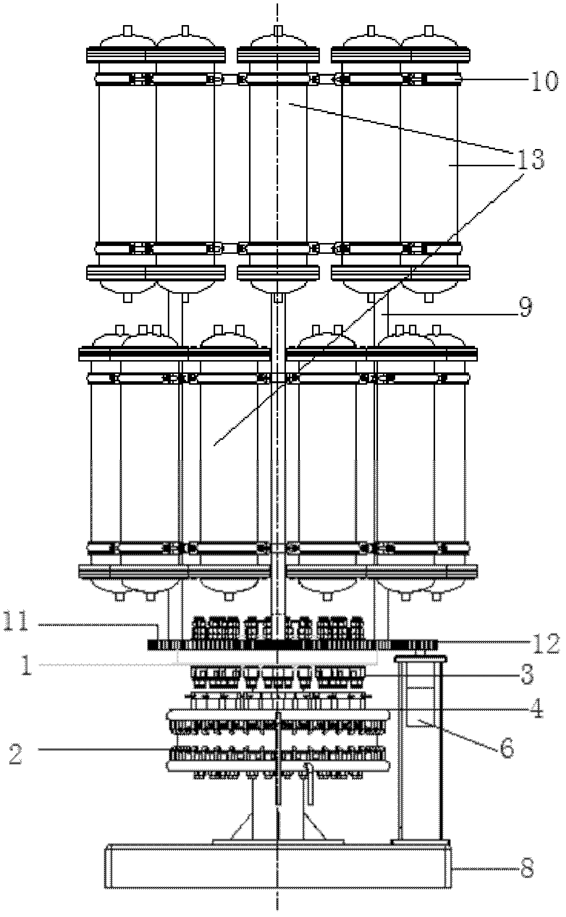
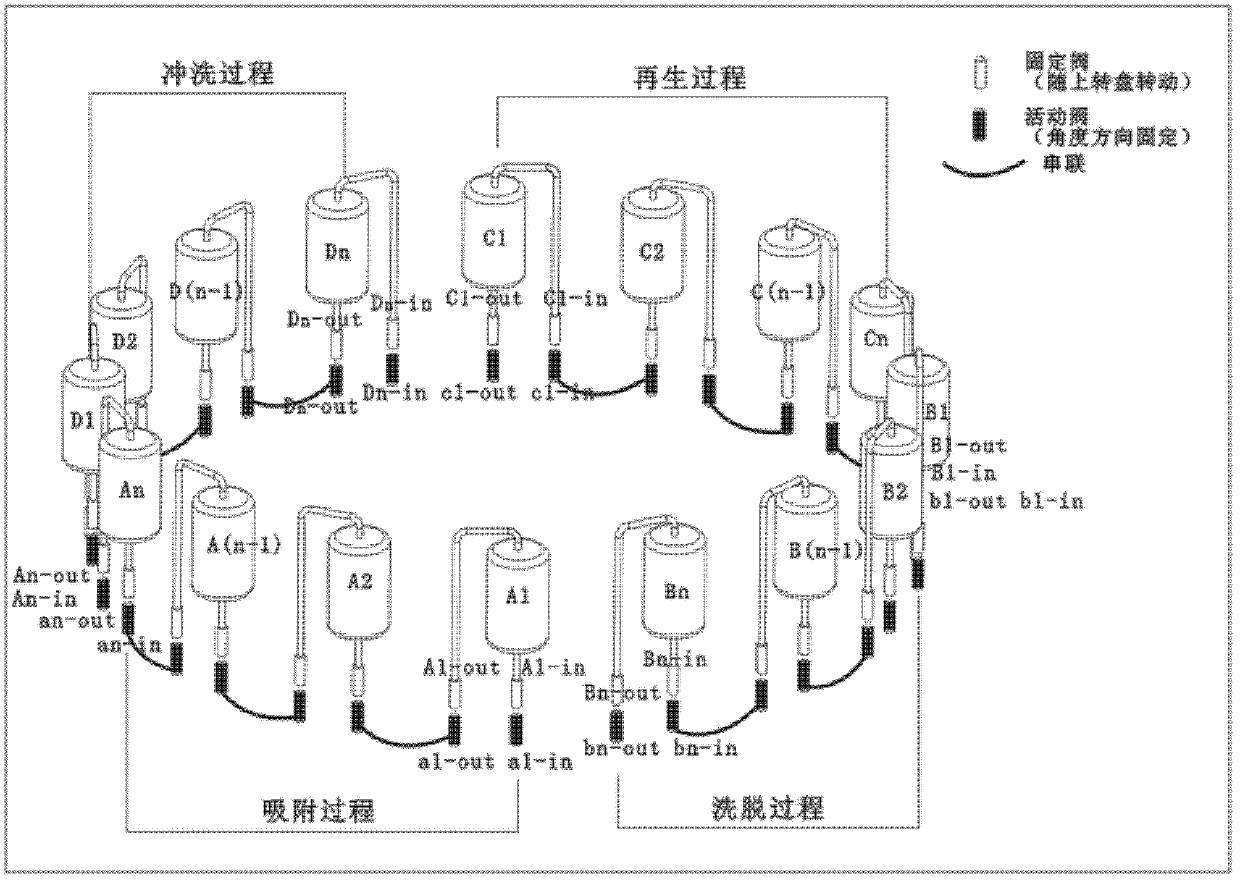
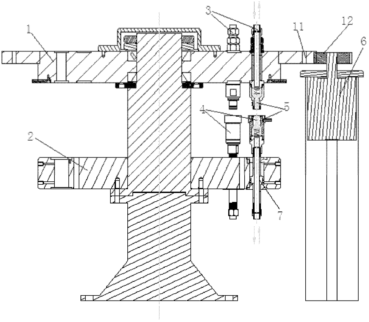
[0043] like Figure 1 to Figure 3 The shown continuous ion adsorption exchange equipment system includes a resin tank and a porous distribution valve, and the porous distribution valve includes a fixed valve array and a movable valve array; the movable valve and the fixed valve have two upper and lower ports, The inlet of each said resin tank is communicated with the upper port of one said fixed valve, and the outlet is communicated with the upper port of another fixed valve; the upper port of said movable valve and the lower port of corresponding said fixed valve are in ...


PUM


Abstract

A continuous ionic adsorption and exchange device system comprises resin tanks and a porous distributing valve, wherein the porous distributing valve comprises a fixed valve array and a movable valve array. Each movable valve and each fixed valve are respectively provided with an upper port and a lower port, an inlet of each resin tank is communicated with the upper port of one fixed valve, and an outlet of each resin tank is communicated with the upper port of another fixed valve, the upper ports of the movable valves are in one-to-one butting design with the lower ports of the fixed valves in the working process, and the lower ports of the movable valves are communicated with each other or communicated with the outside. The continuous ionic adsorption and exchange device system is compact in device, simplified in system, reduced in pipeline and small in occupation area, overcomes the shortcomings of bias current phenomena easily occurring in the adsorption process, vacancy and wasteof partial resin, low using efficiency of resin, large using amount and serve waste of chemical agents in the desorption and regenerative process, large discharging amount of effluent, long operationperiod, large quantity of connection pipelines and valves, fussy operation and the like.

Description

technical field [0001] The invention relates to the technical field of highly refined electrowinning of heavy metals in hydrometallurgy, in particular to a continuous ion adsorption exchange equipment system. Background technique [0002] Continuous ion exchange is a world-recognized advanced separation technology. my country's continuous ion exchange equipment was introduced from Finland by a company in Xiamen around 2002. It is first applied in the purification of antibiotics and Vc in the pharmaceutical industry, and then gradually applied in biological extraction, food and beverage, chemical industry and environmental protection. However, the cost of the equipment is expensive, and it is difficult to popularize and apply it in hydrometallurgy. [0003] Disadvantages of foreign continuous ion exchange equipment: [0004] a) The structure is complex and the cost is high. The price of a continuous ion exchange equipment that can process 5,000 cubic meters of leachate per...

Claims


Application Information

Patent Timeline
Patent Type & Authority Patents(China)
IPC IPC(8): B01J49/00B01J47/00
CPCY02P10/20
Inventor 邱建宁徐纯理赵路李新华杨斗
Owner 关宏强
Why Eureka
Try Eureka