
Vibration monitoring system for transformer

A vibration monitoring system and transformer technology, applied in vibration testing, signal transmission systems, non-electrical signal transmission systems, etc., can solve the problems of difficulty in determining the precise time of detection sensors, poor anti-interference performance, and inability to synchronize data acquisition of all channels, etc. Achieve the effects of high dynamic range, high SNR, and enhanced anti-interference ability

Inactive Publication Date: 2012-08-08
SHANGHAI JIAO TONG UNIV +1
View PDF7 Cites 17 Cited by
  • Summary
  • Abstract
  • Description
  • Claims
  • Application Information

AI Technical Summary

Problems solved by technology

Most of the existing transformer vibration monitoring devices cannot perform synchronous data collection for all channels, so when analyzing the monitoring signals, it is difficult to determine the precise time when the fault signal reaches each detection sensor, and the field anti-interference performance is poor

Method used


Image

  • Vibration monitoring system for transformer
  • Vibration monitoring system for transformer
  • Vibration monitoring system for transformer

Examples


Embodiment Construction

[0027] The present invention will be further described below with reference to the embodiments and accompanying drawings, but the protection scope of the present invention should not be limited by this.

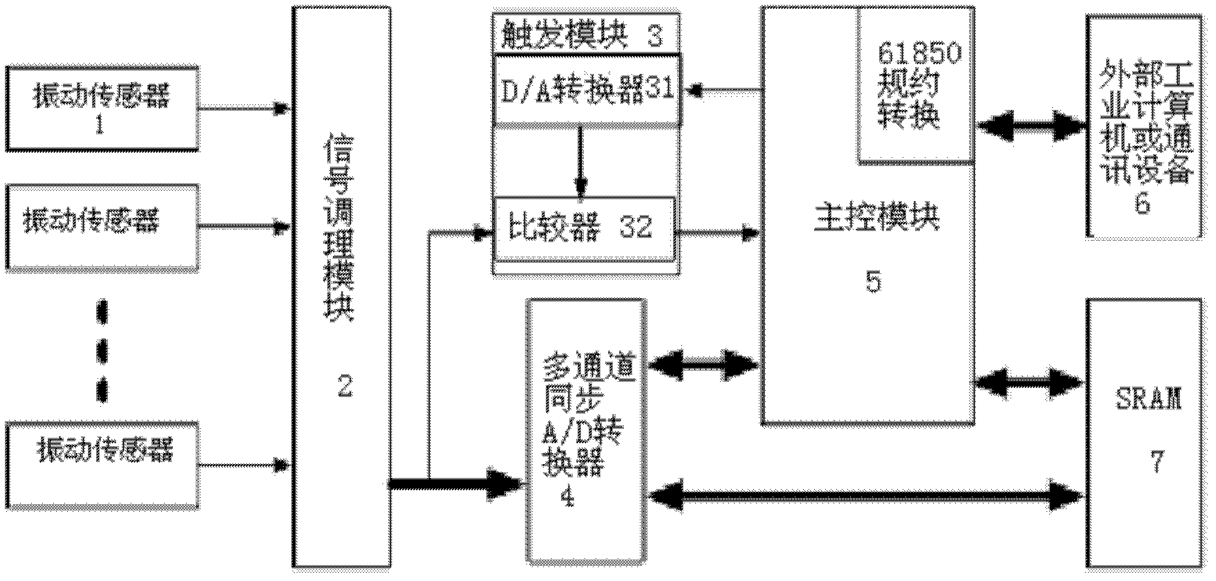
[0028] see first figure 1 , figure 1 It is a schematic structural diagram of the transformer vibration monitoring system of the present invention. As shown in the figure, the transformer vibration monitoring system of the present invention includes: six vibration sensors 1, a signal conditioning module 2, a trigger module 3, a multi-channel A / D converter 4, The main control module 5, the external industrial computer 6 and the high-speed static cache module 7; the connection relationship of the above components is as follows:

[0029] The six vibration sensors 1 are respectively arranged on the six vibration test points of the transformer to be tested, and the output signal connectors of the six vibration sensors 1 are respectively connected with the six input signal connecto...


PUM

PropertyMeasurementUnit
Frequency rangeaaaaaaaaaa
Resolutionaaaaaaaaaa
Sensitivityaaaaaaaaaa

Abstract

The invention provides a vibration monitoring system for a transformer. The vibration monitoring system comprises six vibration sensors which are respectively arranged at six vibration test points of the transformer. An output signal joint of each vibration sensor is connected with an input signal joint of a signal conditioning module; six signal output channels of the signal conditioning module are connected with six signal input channels of a multi-channel A / D (Analogue / Digital) converter; one signal output channel of the signal conditioning module is connected with one signal input channel of a comparer; a signal output channel of the comparer is connected with a control signal input channel of the main control module; a control signal output channel of the main control module is connected with a signal input channel of a D / A (Digital / Analogue) converter in a triggering module; and a data bus of the multi-channel A / D converter is connected with a data bus of the main control module and a data bus of an SRAM (Static Random Access Memory). With the adoption of the vibration monitoring system provided by the invention, the synchronous data collection of the vibration signals of the transformer can be realized by utilizing technology of multiplexing a power supply and a signal wire. The working stability of the vibration sensors can be ensured, and the anti-jamming capability of signals is enhanced, so that the harmonic wave of the transformer at each frequency can be actually reflected by output signals, and the measurement precision of the data is higher.

Description

technical field [0001] The invention relates to an on-line monitoring system for power equipment, in particular to a transformer vibration monitoring system. Background technique [0002] During the long-term operation of the transformer, due to the influence of external environmental factors, various faults will inevitably occur, which will affect the normal operation of the transformer. If it is not discovered in time and appropriate repair measures are taken, the defects will continue to develop, resulting in accidents. . Vibration monitoring has the characteristics of simple installation, sensitive monitoring, and safe and reliable online monitoring without electrical connection between the entire measurement system and the power system. It overcomes the shortcomings of traditional methods and shows a good development prospect in monitoring the condition of transformer windings and iron cores. . Therefore, the application of vibration method to monitor power transforme...

Claims


Application Information

Patent Timeline
IPC IPC(8): G01M7/02G08C23/06G08C23/04
Inventor 严英杰刘亚东朱俊盛戈皞杜凤青朱柳惠江秀臣
Owner SHANGHAI JIAO TONG UNIV
Learn More