Heat dissipation system of integrated circuit tester and control method thereof

An integrated circuit and heat dissipation system technology, which is applied in the field of integrated circuit tester heat dissipation system, can solve the problems of large power loss and noise pollution, and achieve the effects of reducing power consumption and noise, solving large power loss, and solving serious noise pollution

Active Publication Date: 2012-08-08
深圳米飞泰克科技股份有限公司
View PDF6 Cites 6 Cited by
  • Summary
  • Abstract
  • Description
  • Claims
  • Application Information

AI Technical Summary

Problems solved by technology

[0004] The object of the present invention is to provide a heat dissipation system for integrated circuit testers, aiming to solve the problems of large power loss and serious noise pollution in existing heat dissipation systems for integrated circuit testers

Method used


Image

  • Heat dissipation system of integrated circuit tester and control method thereof
  • Heat dissipation system of integrated circuit tester and control method thereof
  • Heat dissipation system of integrated circuit tester and control method thereof

Examples


Embodiment 1

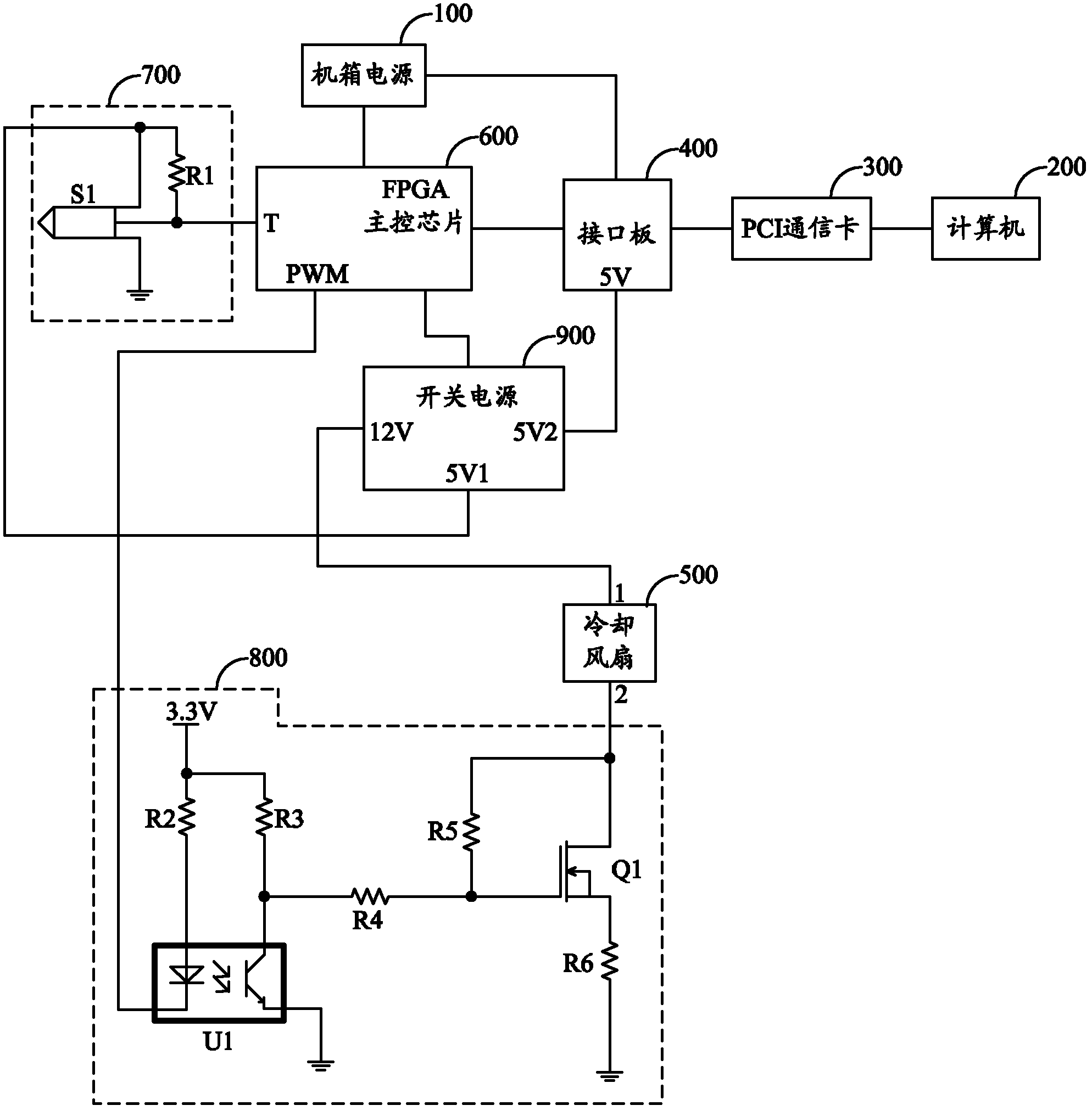
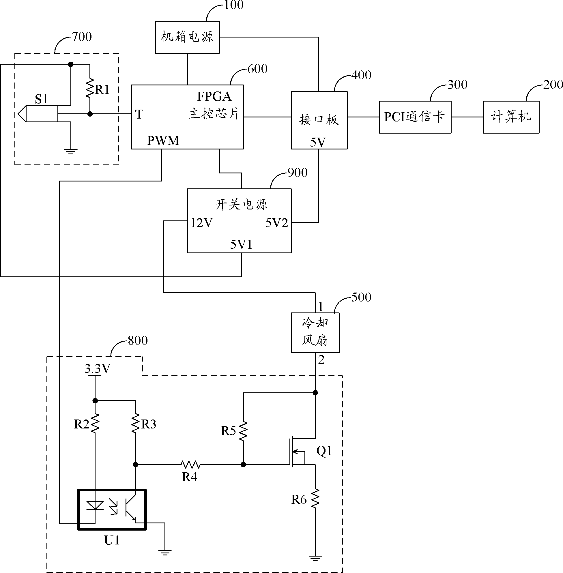
[0024] figure 1 An example circuit structure of the heat dissipation system of the integrated circuit tester provided by the first embodiment of the present invention is shown. For the convenience of description, only the parts related to the first embodiment of the present invention are shown, and the details are as follows:

[0025] A heat dissipation system for an integrated circuit tester, connected to a chassis power supply 100 of the integrated circuit tester, including a computer 200, a PCI communication card 300, an interface board 400 and a cooling fan 500, the integrated circuit tester heat dissipation system also includes:

[0026] The FPGA main control chip 600 is connected with the chassis power supply 100 and the interface board 400, and is used to control the peripheral equipment units accordingly according to the control instructions of the computer 200;

[0027] The temperature sensing unit 700 is arranged outside the chassis of the integrated circuit tester a...

Embodiment 2

[0038] In the embodiment of the present invention, the cooling system of the integrated circuit tester in the first embodiment is used to monitor the chassis temperature of the integrated circuit tester, and output a low-frequency pulse width modulation signal to adjust the speed of the cooling fan according to the change of the chassis temperature, thereby To achieve the purpose of reducing power consumption and noise.

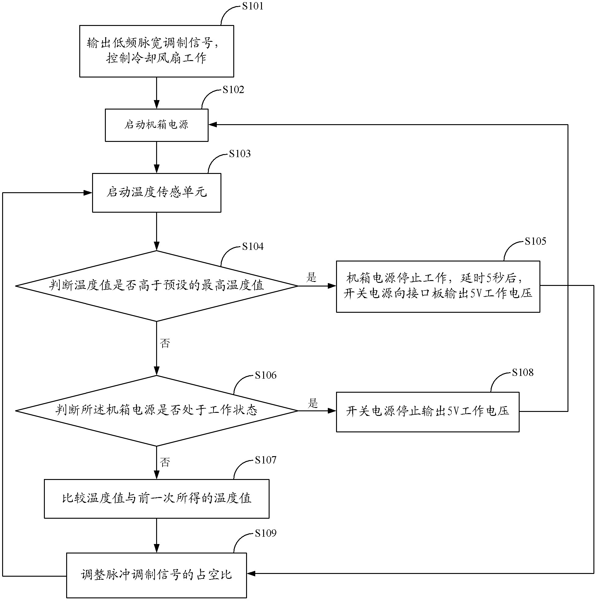
[0039] figure 2 It shows the implementation process of the heat dissipation control method of the integrated circuit tester provided by the second embodiment of the present invention. For the convenience of description, only the parts related to the second embodiment of the present invention are shown, and the details are as follows:

[0040] The method for controlling the cooling system of an integrated circuit tester includes the following steps:

[0041] Step 101, outputting a low-frequency pulse width modulation signal to control the cooling fan to work...


PUM


Abstract

The invention, which belongs to the temperature control field, provides a heat dissipation system of an integrated circuit tester and a control method thereof. According to the invention, a heat dissipation system of an integrated circuit tester uses a field programmable gate array (FPGA) master control chip as a core; a temperature sensing unit is utilized to carry out sensing on a temperature of a cabinet of the integrated circuit tester; and the FPGA master control chip is used to determine whether the sensed temperature is higher than a cabinet temperature obtained previously and a low frequency pulse width modulation signal output by the FPGA master control chip itself is adjusted. Therefore, control on a rotating speed of a cooling fan can be realized; an objective of reduction of power consumption and noises is achieved; and problems of large power loss and severe noise pollution are solved, wherein the problems exist in a heat dissipation system of a current integrated heat dissipation system.

Description

technical field [0001] The invention belongs to the field of temperature control, in particular to a cooling system and method for an integrated circuit tester. Background technique [0002] At present, the tester used in the integrated circuit production line, due to the continuous operation, the temperature of the tester case rises. When the temperature is too high, the components of the tester are prone to overheating failure or damage. Therefore, in the existing heat dissipation system, a cooling fan is provided outside the IC tester, and the purpose of cooling the IC tester is achieved by controlling the cooling fan to keep running at a certain speed. [0003] However, in the existing heat dissipation system, only the cooling fan is continuously operated at a constant speed to achieve the purpose of cooling the integrated circuit tester, and this heat dissipation method needs to be at the cost of extra power consumption. Because the temperature of the IC tester chassis...

Claims


Application Information

Patent Timeline
IPC IPC(8): G01R1/02F25D1/00
Inventor 方盼李显军李志强
Owner 深圳米飞泰克科技股份有限公司
Why Eureka
Try Eureka